esp32开发笔记-基本外设功能测试
1.参考资料
1.1.esp32s3参考原理图
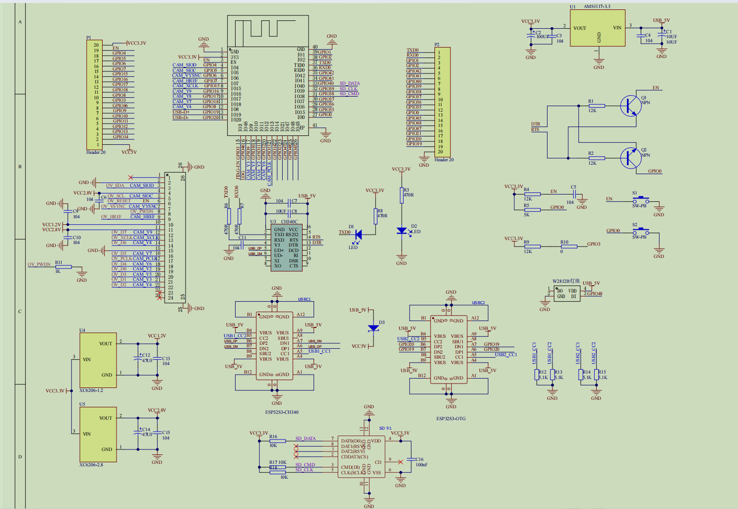
1.2 jtag驱动安装
ESP32S3 内部自带jtag,默认情况下连接ESP32S3的USB带串口和JTAG功能,既能调试程序,在调试程序之前需要安装相应JTAG驱动,驱动的下载地址为:
https://zadig.akeo.ie/ https://zadig.akeo.ie/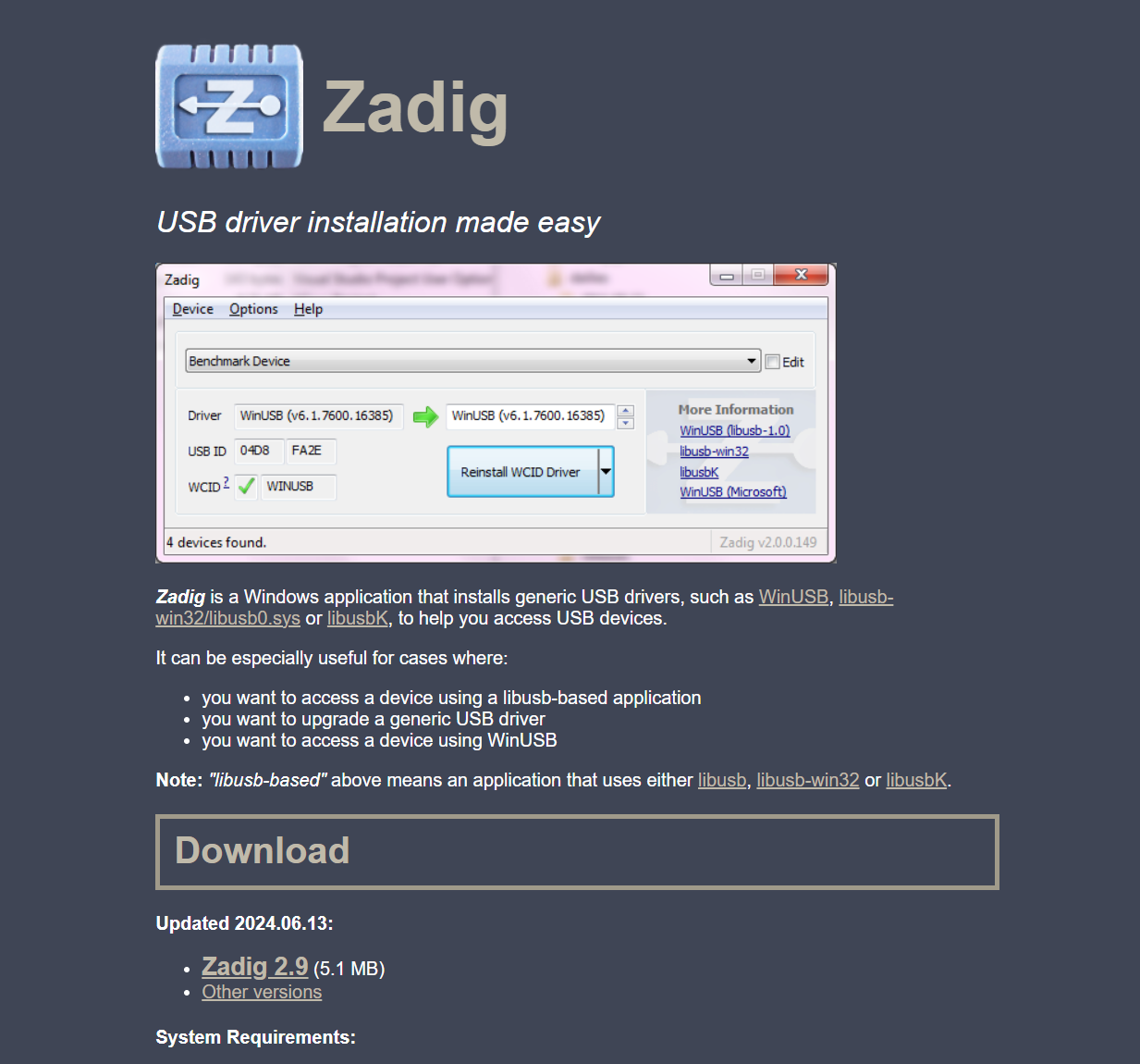
2.ESP32硬件基本介绍
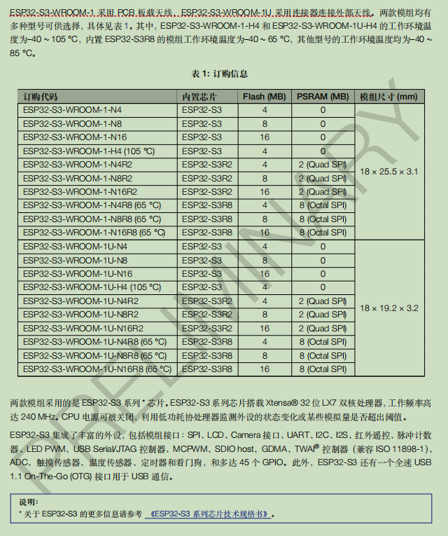
这里使用的是 《ESP32-S3-WROOM-1-n16r8》这个模组,内部封装了16MBflash,和8MByte的PSram,ESP32-S3 芯片有 45 个物理通用输入输出管脚(GPIO Pin)。每个管脚都可用作一个通用输入输出,或连接一个内部外设信号。利用 GPIO 交换矩阵、IO MUX(IO 复用选择器)和 RTC IO MUX(RTC 复用选择器),可配置外设模块的输入信号来源于任何的 GPIO 管脚,并且外设模块的输出信号也可连接到任意 GPIO 管脚。这些模块共同组成了芯片的输入输出控制。
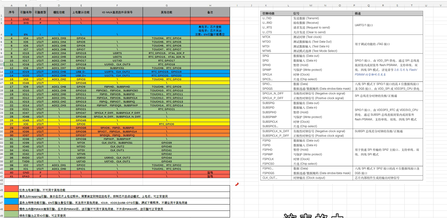
值得注意的是,这 45 个物理 GPIO 管脚的编号为 0~21、26~48。这些管脚即可作为输入有可作为输出管脚。使用时需要注意存储占用的引脚最好不要使用。
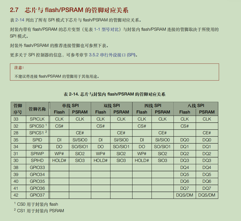
ESP32-S3-WROOM-1-N16R8 模组作为主控,但该模组只有 36 个实际引脚的物理 GPIO 管脚。这是因为该模组的 Flash 和 PSRAM 使用了八线 SPI即 Octal SPI 模式,这些模式共占用了 12 个 GPIO 管脚。而且,该模组还将 IO35、IO36、IO37引出,所以最终的管脚数量为 45-12+3,即 36 个 GPIO 管脚。

GPIO使用注意:需要避开内部的PSRAM和Flash使用的引脚。
在数据手册中有相关引脚描述:
关于官方模组资料请查看:
esp32-s3-wroom-1_wroom-1u_datasheet_cn.pdf
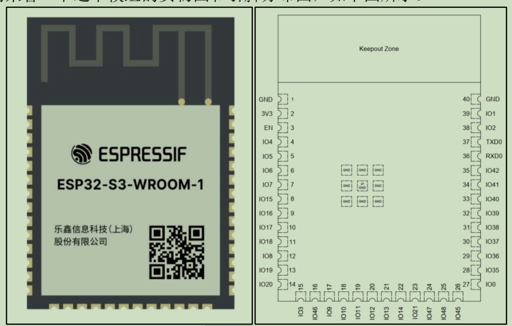
总结引脚功能如图所示:
3.基本外设操作
esp32有许多外设,有单片机基础,再去学每个外设怎么用,这样进度很慢,而且每个外设用的库编程,我们只需要看下数据手册分析自己要用的外设即可,至于具体外设怎么用库去配置,我们应该参考官方的SDK例子,在例子的基础上编写。
3.1基本外设参考地址github:
3.2外设硬件设计参考:
3.3 通用工程创建
使用vscode创建一个新工程,并配置工程(配置过程参考:https://blog.csdn.net/klp1358484518/article/details/160014016?sharetype=blogdetail&sharerId=160014016&sharerefer=PC&sharesource=klp1358484518&spm=1011.2480.3001.8118https://blog.csdn.net/klp1358484518/article/details/160014016?sharetype=blogdetail&sharerId=160014016&sharerefer=PC&sharesource=klp1358484518&spm=1011.2480.3001.8118或者使用现成工程:https://download.csdn.net/download/klp1358484518/92796836https://download.csdn.net/download/klp1358484518/92796836),再创建gpio组件。
自定义组件绝对不能和系统内置组件重名内置组件列表:gpio、uart、i2c、spi、wifi 等……
4 gpio例子
4.1 官方GPIO外设和API参考资料
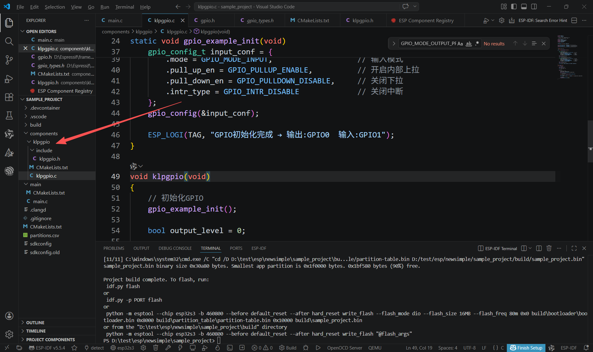
4.2 添加klpgpio组件
新建工程并添加自定义组件如图:
4.3 示例代码
#include <stdio.h>
#include "klpgpio.h"
/*
 * ESP32-S3 N16R8 基础GPIO输入输出示例
 * 严格避开内部Flash/PSRAM占用引脚
 */
#include <stdio.h>
#include "freertos/FreeRTOS.h"
#include "freertos/task.h"
#include "driver/gpio.h"
#include "esp_log.h"

// 日志标签
static const char *TAG = "GPIO_TEST";

// ===================== 安全GPIO定义 =====================
#define GPIO_OUTPUT_PIN     GPIO_NUM_0  // 输出引脚(绝对安全)
#define GPIO_INPUT_PIN      GPIO_NUM_1  // 输入引脚(绝对安全)
// ========================================================

/**
 * @brief GPIO初始化
 */
static void gpio_example_init(void)
{
    // 1. 配置输出引脚
    gpio_config_t output_conf = {
        .pin_bit_mask = (1ULL << GPIO_OUTPUT_PIN), // 选中引脚
        .mode = GPIO_MODE_OUTPUT,                   // 输出
        .pull_up_en = GPIO_PULLUP_DISABLE,         // 关闭上拉
        .pull_down_en = GPIO_PULLDOWN_DISABLE,     // 关闭下拉
        .intr_type = GPIO_INTR_DISABLE             // 关闭中断
    };
    gpio_config(&output_conf);

    // 2. 配置输入引脚(内部上拉,按键常用)
    gpio_config_t input_conf = {
        .pin_bit_mask = (1ULL << GPIO_INPUT_PIN),  // 选中引脚
        .mode = GPIO_MODE_INPUT,                   // 输入模式
        .pull_up_en = GPIO_PULLUP_ENABLE,          // 开启内部上拉
        .pull_down_en = GPIO_PULLDOWN_DISABLE,     // 关闭下拉
        .intr_type = GPIO_INTR_DISABLE             // 关闭中断
    };
    gpio_config(&input_conf);

    ESP_LOGI(TAG, "GPIO初始化完成 → 输出:GPIO0  输入:GPIO1");
}

void klpgpio(void)
{
    // 初始化GPIO
    gpio_example_init();

    bool output_level = 0;

    // 主循环
    while (1) {
        // 1. 翻转输出电平
        output_level = !output_level;
        gpio_set_level(GPIO_OUTPUT_PIN, output_level);

        // 2. 读取输入电平
        int input_level = gpio_get_level(GPIO_INPUT_PIN);

        // 3. 打印状态
        ESP_LOGI(TAG, "输出电平: %d | 输入电平: %d", output_level, input_level);

        // 延时500ms
        vTaskDelay(pdMS_TO_TICKS(500));
    }
}
4.4 CMakeLists.txt修改
components\klpgpio\CMakeLists.txt 的修改:
idf_component_register(SRCS "klpgpio.c"
                    INCLUDE_DIRS "include"
                    REQUIRES esp_driver_gpio)
5.红外遥控 (RMT)驱动ws2812
5.1 创建组件和添加扩展组件
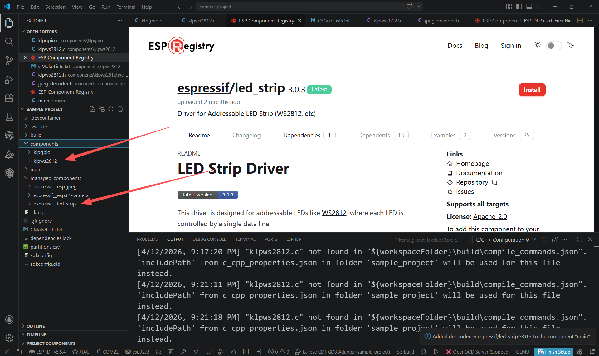
5.2 编写代码
#include <stdio.h>
#include "klpws2812.h"
/*
 * SPDX-FileCopyrightText: 2023-2024 Espressif Systems (Shanghai) CO LTD
 *
 * SPDX-License-Identifier: Unlicense OR CC0-1.0
 */
#include <stdio.h>
#include "freertos/FreeRTOS.h"
#include "freertos/task.h"
#include "led_strip.h"
#include "esp_log.h"
#include "esp_err.h"

// Set to 1 to use DMA for driving the LED strip, 0 otherwise
// Please note the RMT DMA feature is only available on chips e.g. ESP32-S3/P4
#define LED_STRIP_USE_DMA  1

#if LED_STRIP_USE_DMA
// Numbers of the LED in the strip
#define LED_STRIP_LED_COUNT 1
#define LED_STRIP_MEMORY_BLOCK_WORDS 1024 // this determines the DMA block size
#else
// Numbers of the LED in the strip
#define LED_STRIP_LED_COUNT 24
#define LED_STRIP_MEMORY_BLOCK_WORDS 0 // let the driver choose a proper memory block size automatically
#endif // LED_STRIP_USE_DMA

// GPIO assignment
#define LED_STRIP_GPIO_PIN  GPIO_NUM_48

// 10MHz resolution, 1 tick = 0.1us (led strip needs a high resolution)
#define LED_STRIP_RMT_RES_HZ  (10 * 1000 * 1000)

static const char *TAG = "example";

led_strip_handle_t configure_led(void)
{
    // LED strip general initialization, according to your led board design
    led_strip_config_t strip_config = {
        .strip_gpio_num = LED_STRIP_GPIO_PIN, // The GPIO that connected to the LED strip's data line
        .max_leds = LED_STRIP_LED_COUNT,      // The number of LEDs in the strip,
        .led_model = LED_MODEL_WS2812,        // LED strip model
        .color_component_format = LED_STRIP_COLOR_COMPONENT_FMT_GRB, // The color order of the strip: GRB
        .flags = {
            .invert_out = false, // don't invert the output signal
        }
    };

    // LED strip backend configuration: RMT
    led_strip_rmt_config_t rmt_config = {
        .clk_src = RMT_CLK_SRC_DEFAULT,        // different clock source can lead to different power consumption
        .resolution_hz = LED_STRIP_RMT_RES_HZ, // RMT counter clock frequency
        .mem_block_symbols = LED_STRIP_MEMORY_BLOCK_WORDS, // the memory block size used by the RMT channel
        .flags = {
            .with_dma = LED_STRIP_USE_DMA,     // Using DMA can improve performance when driving more LEDs
        }
    };

    // LED Strip object handle
    led_strip_handle_t led_strip;
    ESP_ERROR_CHECK(led_strip_new_rmt_device(&strip_config, &rmt_config, &led_strip));
    ESP_LOGI(TAG, "Created LED strip object with RMT backend");
    return led_strip;
}

void ws2812(void)
{
    led_strip_handle_t led_strip = configure_led();
    bool led_on_off = false;

    ESP_LOGI(TAG, "Start blinking LED strip");
    while (1) {
        if (led_on_off) {
            /* Set the LED pixel using RGB from 0 (0%) to 255 (100%) for each color */
            for (int i = 0; i < LED_STRIP_LED_COUNT; i++) {
                ESP_ERROR_CHECK(led_strip_set_pixel(led_strip, i, 5, 25, 5));
            }
            /* Refresh the strip to send data */
            ESP_ERROR_CHECK(led_strip_refresh(led_strip));
            ESP_LOGI(TAG, "LED ON!");
        } else {
            /* Set all LED off to clear all pixels */
            ESP_ERROR_CHECK(led_strip_clear(led_strip));
            ESP_LOGI(TAG, "LED OFF!");
        }

        led_on_off = !led_on_off;
        vTaskDelay(pdMS_TO_TICKS(500));
    }
}
5.3 修改CMakelists.txt
idf_component_register(SRCS "klpws2812.c"
                    INCLUDE_DIRS "include"
                    REQUIRES espressif__led_strip )
6.LCD_CAM测试
6.1 安装摄像头组件
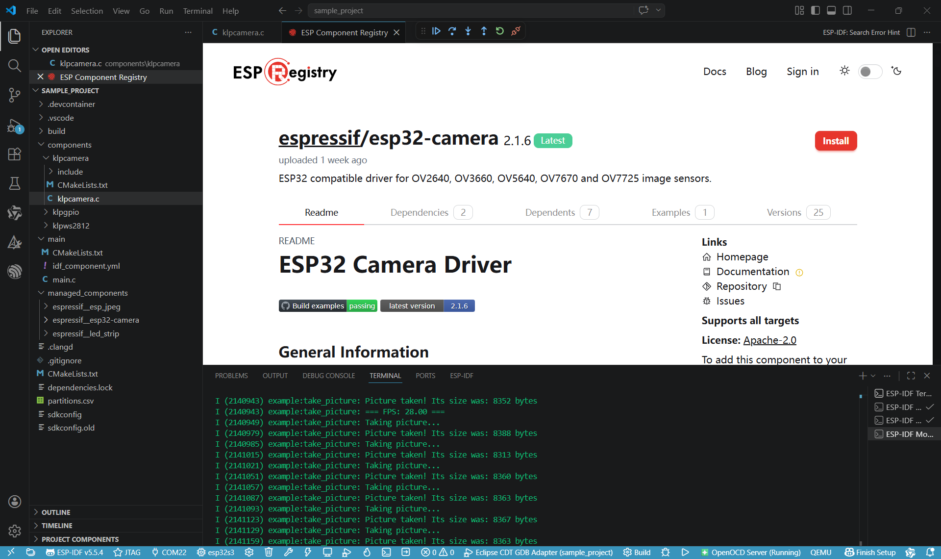
在esp32s3中RGB LCD接口和摄像头DVP接口依赖相同硬件,所以两个功能不能同时使用,如果需要使用lcd建议使用spi接口的lcd。官方有比较完善的摄像头组件 espressif__esp32-camera 可以直接使用,在vscode搜索 camera 安装组件,他会同时安装 espressif/esp_jpeg ^1.3.1 这个依赖。
6.2 创建自定义组件
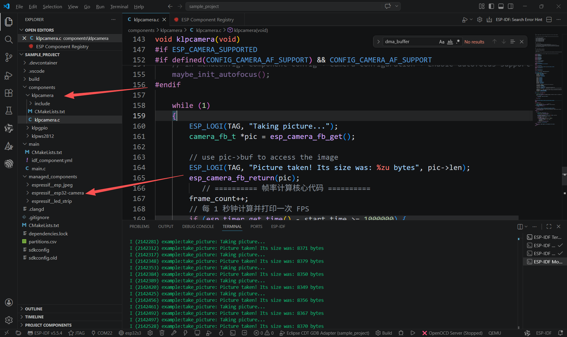
创建一个自定义的 klpcamera 组件使用这个 espressif__esp32-camera 组件,最后工程如图所示:
6.3 示例代码
使用 espressif__esp32-camera 组件的例子程序,直接进行摄像头的功能测试,源码路径如图所示:
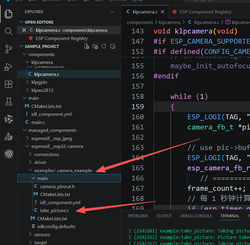
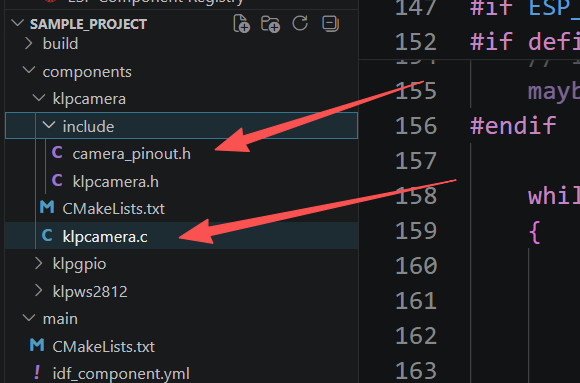
复制 camera_pinout.h 这个文件到自己工程目录,并修改引脚的宏定义为自己摄像头硬件使用的引脚,复制例子源码到自己工程的 klpcamera.c 文件里面修改代码,最后在main.c的 void app_main(void) 函数中调用测试摄像头的函数 void klpcamera(void) 会打印帧率和每张jpeg图片占用的内存容量。
camera_pinout.h 源码修改:
// WROVER-KIT PIN Map
#ifdef BOARD_WROVER_KIT

#define CAM_PIN_PWDN GPIO_NUM_NC  //power down is not used
#define CAM_PIN_RESET GPIO_NUM_NC //software reset will be performed
#define CAM_PIN_XCLK GPIO_NUM_15
#define CAM_PIN_SIOD GPIO_NUM_4
#define CAM_PIN_SIOC GPIO_NUM_5

#define CAM_PIN_D7 GPIO_NUM_16
#define CAM_PIN_D6 GPIO_NUM_17
#define CAM_PIN_D5 GPIO_NUM_18
#define CAM_PIN_D4 GPIO_NUM_12
#define CAM_PIN_D3 GPIO_NUM_10
#define CAM_PIN_D2 GPIO_NUM_8
#define CAM_PIN_D1 GPIO_NUM_9
#define CAM_PIN_D0 GPIO_NUM_11
#define CAM_PIN_VSYNC GPIO_NUM_6
#define CAM_PIN_HREF GPIO_NUM_7
#define CAM_PIN_PCLK GPIO_NUM_13

#endif

// ESP32Cam (AiThinker) PIN Map
#ifdef BOARD_ESP32CAM_AITHINKER

#define CAM_PIN_PWDN 32
#define CAM_PIN_RESET -1 //software reset will be performed
#define CAM_PIN_XCLK 0
#define CAM_PIN_SIOD 26
#define CAM_PIN_SIOC 27

#define CAM_PIN_D7 35
#define CAM_PIN_D6 34
#define CAM_PIN_D5 39
#define CAM_PIN_D4 36
#define CAM_PIN_D3 21
#define CAM_PIN_D2 19
#define CAM_PIN_D1 18
#define CAM_PIN_D0 5
#define CAM_PIN_VSYNC 25
#define CAM_PIN_HREF 23
#define CAM_PIN_PCLK 22

#endif
// ESP32S3 (WROOM) PIN Map
#ifdef BOARD_ESP32S3_WROOM
#define CAM_PIN_PWDN 38
#define CAM_PIN_RESET -1   //software reset will be performed
#define CAM_PIN_VSYNC 6
#define CAM_PIN_HREF 7
#define CAM_PIN_PCLK 13
#define CAM_PIN_XCLK 15
#define CAM_PIN_SIOD 4
#define CAM_PIN_SIOC 5
#define CAM_PIN_D0 11
#define CAM_PIN_D1 9
#define CAM_PIN_D2 8
#define CAM_PIN_D3 10
#define CAM_PIN_D4 12
#define CAM_PIN_D5 18
#define CAM_PIN_D6 17
#define CAM_PIN_D7 16
#endif
// ESP32S3 (GOOUU TECH)
#ifdef BOARD_ESP32S3_GOOUUU
#define CAM_PIN_PWDN -1
#define CAM_PIN_RESET -1   //software reset will be performed
#define CAM_PIN_VSYNC 6
#define CAM_PIN_HREF 7
#define CAM_PIN_PCLK 13
#define CAM_PIN_XCLK 15
#define CAM_PIN_SIOD 4
#define CAM_PIN_SIOC 5
#define CAM_PIN_D0 11
#define CAM_PIN_D1 9
#define CAM_PIN_D2 8
#define CAM_PIN_D3 10
#define CAM_PIN_D4 12
#define CAM_PIN_D5 18
#define CAM_PIN_D6 17
#define CAM_PIN_D7 16
#endif
// ESP32S3 (XIAO)
#ifdef BOARD_ESP32S3_XIAO
#define CAM_PIN_PWDN -1
#define CAM_PIN_RESET -1   //software reset will be performed
#define CAM_PIN_VSYNC 38
#define CAM_PIN_HREF 47
#define CAM_PIN_PCLK 13
#define CAM_PIN_XCLK 10
#define CAM_PIN_SIOD 40
#define CAM_PIN_SIOC 39
#define CAM_PIN_D0 15
#define CAM_PIN_D1 17
#define CAM_PIN_D2 18
#define CAM_PIN_D3 16
#define CAM_PIN_D4 14
#define CAM_PIN_D5 12
#define CAM_PIN_D6 11
#define CAM_PIN_D7 48
#endif
klpcamera.c 源码修改
/**
 * This example takes a picture every 5s and print its size on serial monitor.
 */

// =============================== SETUP ======================================

// 1. Board setup (Uncomment):
// #define BOARD_WROVER_KIT
// #define BOARD_ESP32CAM_AITHINKER
// #define BOARD_ESP32S3_WROOM
// #define BOARD_ESP32S3_XIAO
// #define BOARD_ESP32S3_GOOUUU
// #define BOARD_ESP32S3_XIAO

/**
 * 2. Kconfig setup
 *
 * If you have a Kconfig file, copy the content from
 *  https://github.com/espressif/esp32-camera/blob/master/Kconfig into it.
 * In case you haven't, copy and paste this Kconfig file inside the src directory.
 * This Kconfig file has definitions that allows more control over the camera and
 * how it will be initialized.
 */

/**
 * 3. Enable PSRAM on sdkconfig:
 *
 * CONFIG_ESP32_SPIRAM_SUPPORT=y
 *
 * More info on
 * https://docs.espressif.com/projects/esp-idf/en/latest/esp32/api-reference/kconfig.html#config-esp32-spiram-support
 */

// ================================ CODE ======================================
#include <stdio.h>
#include "klpcamera.h"
#include <esp_timer.h>
#include "sdkconfig.h"

#include <esp_log.h>
#include <esp_system.h>
#include <nvs_flash.h>
#include <sys/param.h>
#include <string.h>

#include "freertos/FreeRTOS.h"
#include "freertos/task.h"

// support IDF 5.x
#ifndef portTICK_RATE_MS
#define portTICK_RATE_MS portTICK_PERIOD_MS
#endif

#include "esp_camera.h"

#if defined(CONFIG_CAMERA_AF_SUPPORT) && CONFIG_CAMERA_AF_SUPPORT
#include "esp_camera_af.h"
#endif

#define BOARD_WROVER_KIT 1

#include "camera_pinout.h"

static const char *TAG = "example:take_picture";

#if ESP_CAMERA_SUPPORTED
static camera_config_t camera_config = {
    .pin_pwdn = CAM_PIN_PWDN,
    .pin_reset = CAM_PIN_RESET,
    .pin_xclk = CAM_PIN_XCLK,
    .pin_sccb_sda = CAM_PIN_SIOD,
    .pin_sccb_scl = CAM_PIN_SIOC,

    .pin_d7 = CAM_PIN_D7,
    .pin_d6 = CAM_PIN_D6,
    .pin_d5 = CAM_PIN_D5,
    .pin_d4 = CAM_PIN_D4,
    .pin_d3 = CAM_PIN_D3,
    .pin_d2 = CAM_PIN_D2,
    .pin_d1 = CAM_PIN_D1,
    .pin_d0 = CAM_PIN_D0,
    .pin_vsync = CAM_PIN_VSYNC,
    .pin_href = CAM_PIN_HREF,
    .pin_pclk = CAM_PIN_PCLK,

    //XCLK 20MHz or 10MHz for OV2640 double FPS (Experimental)
    .xclk_freq_hz = 20000000,
    .ledc_timer = LEDC_TIMER_0,
    .ledc_channel = LEDC_CHANNEL_0,

    .pixel_format = PIXFORMAT_JPEG, //YUV422,GRAYSCALE,RGB565,JPEG
    .frame_size = FRAMESIZE_VGA,    //QQVGA-UXGA, For ESP32, do not use sizes above QVGA when not JPEG. The performance of the ESP32-S series has improved a lot, but JPEG mode always gives better frame rates.

    .jpeg_quality = 12, //0-63, for OV series camera sensors, lower number means higher quality
    .fb_count = 5,       //When jpeg mode is used, if fb_count more than one, the driver will work in continuous mode.
    .fb_location = CAMERA_FB_IN_PSRAM,
    .grab_mode = CAMERA_GRAB_WHEN_EMPTY,
};

static esp_err_t init_camera(void)
{
    //initialize the camera
    esp_err_t err = esp_camera_init(&camera_config);//这里面会自动识别摄像头是OV2640还是OV3660,然后自动初始化
    if (err != ESP_OK)
    {
        ESP_LOGE(TAG, "Camera Init Failed");
        return err;
    }

    return ESP_OK;
}

#if defined(CONFIG_CAMERA_AF_SUPPORT) && CONFIG_CAMERA_AF_SUPPORT
static void maybe_init_autofocus(void)
{
    sensor_t *s = esp_camera_sensor_get();
    if (!s) {
        ESP_LOGW(TAG, "AF: no sensor handle");
        return;
    }

    if (!esp_camera_af_is_supported(s)) {
        ESP_LOGI(TAG, "AF: not supported by this sensor");
        return;
    }

    esp_camera_af_config_t af_cfg = {
        .mode = ESP_CAMERA_AF_MODE_AUTO,
        .timeout_ms = CONFIG_CAMERA_AF_DEFAULT_TIMEOUT_MS,
    };

    esp_err_t ret = esp_camera_af_init(s, &af_cfg);
    if (ret != ESP_OK) {
        ESP_LOGW(TAG, "AF init failed: %s", esp_err_to_name(ret));
        return;
    }

    ESP_LOGI(TAG, "AF initialized (AUTO mode)");
}
#endif
#endif

void klpcamera(void)
{
    uint32_t frame_count = 0;           // 帧数计数器
    int64_t start_time = esp_timer_get_time();  // 起始时间(微秒)
#if ESP_CAMERA_SUPPORTED
    if(ESP_OK != init_camera()) {
        return;
    }

#if defined(CONFIG_CAMERA_AF_SUPPORT) && CONFIG_CAMERA_AF_SUPPORT
    // Initialize autofocus if configured and supported by the sensor.
    // In menuconfig: Component config → Camera configuration → Enable autofocus support
    maybe_init_autofocus();
#endif

    while (1)
    {
        ESP_LOGI(TAG, "Taking picture...");
        camera_fb_t *pic = esp_camera_fb_get();

        // use pic->buf to access the image
        ESP_LOGI(TAG, "Picture taken! Its size was: %zu bytes", pic->len);
        esp_camera_fb_return(pic);
           // ========== 帧率计算核心代码 ==========
        frame_count++;
        // 每 1 秒钟计算并打印一次 FPS
        if (esp_timer_get_time() - start_time >= 1000000) {
            float fps = frame_count;
            ESP_LOGI(TAG, "=== FPS: %.2f ===", fps);
            // 重置计数器
            frame_count = 0;
            start_time = esp_timer_get_time();
        }
        vTaskDelay(5 / portTICK_RATE_MS);
    }
#else
    ESP_LOGE(TAG, "Camera support is not available for this chip");
    return;
#endif
}
6.4 CMakelists.txt修改
idf_component_register(SRCS "klpcamera.c"
                    INCLUDE_DIRS "include"
                    REQUIRES espressif__esp32-camera nvs_flash esp_timer)
6.5 调试结果
编译调试程序,注意需要使用usb连接用vscode的调试功能,输出如图所示:
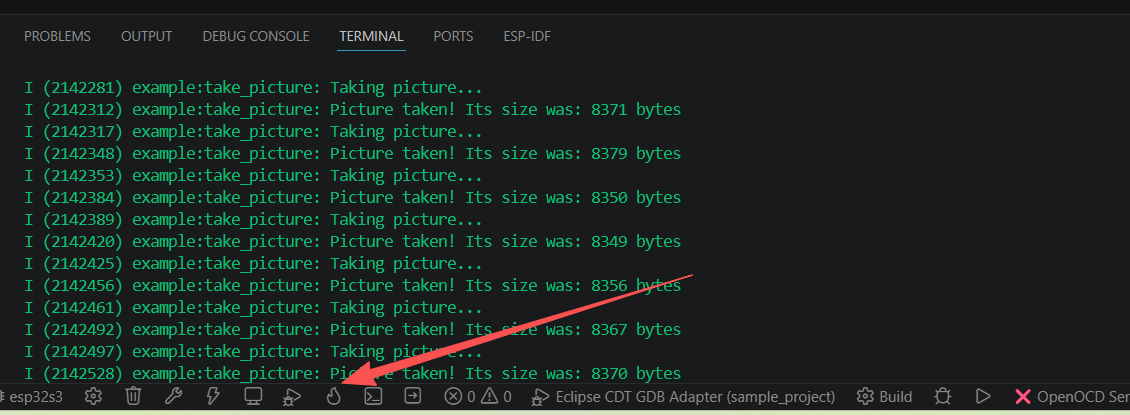
红色箭头标指的是下载调试按钮。
拓展
1.添加依赖的组件
当我们需要使用官方开发的一些组件的时候,需要在 CMakeLists.txt 添加依赖,不知道增加的组件的名字的时候,可以执行:
idf.py reconfigure输出的组件这一行会打印出现在项目里的所有组件如:
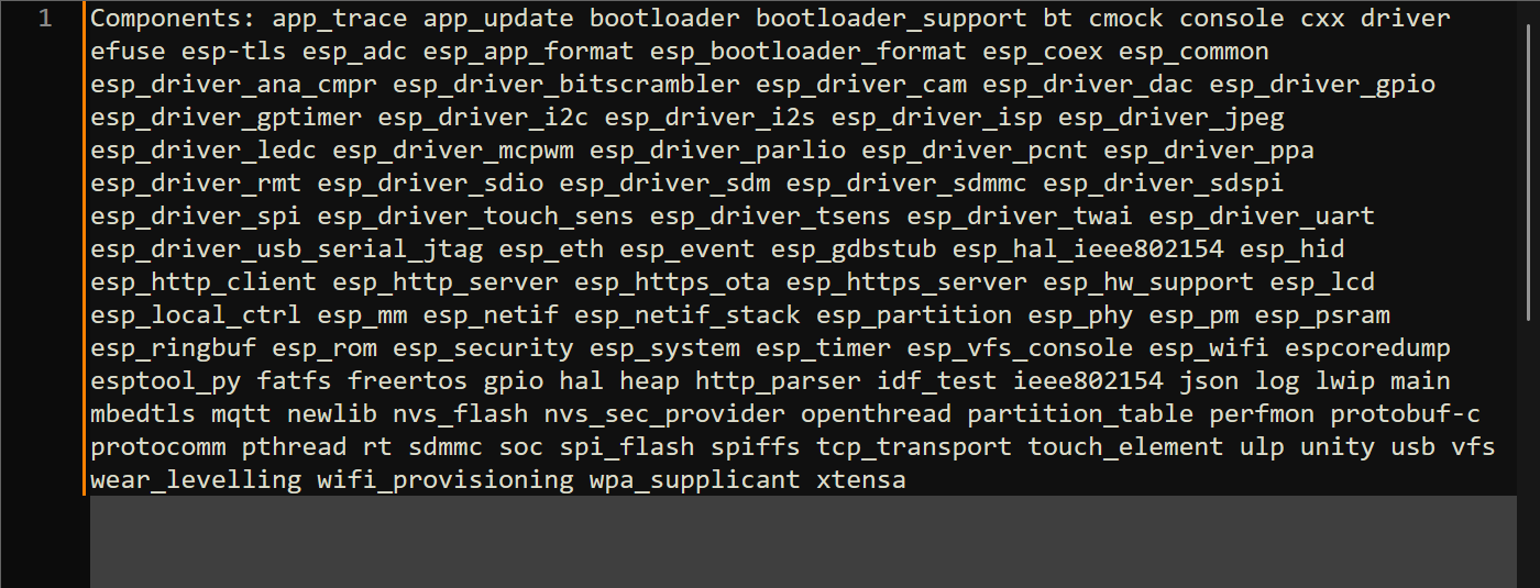
举例现在我添加 esp_driver_gpio 这个组件,我只需要在自己的组件的 CMakelists.txt 里面添加
2.项目代码地址
https://github.com/1358484518/learning_ESP32S3.githttps://github.com/1358484518/learning_ESP32S3.git以上仓库存储测试代码地址,用vscode打开即可使用。
3.esp32开发总结
esp32的GPIO除了个别高速外设和I/O,其他外设都可以使用任意的I/O,通过I/O内部矩阵控制映射I/O到相应的外设,一般做开发的时候,建议一般先AI查一下有没有在线的官方组件和本地的一些组件,可以直接使用他们,而且这些组件的功能一般比较完善,有相应的例子程序,直接复制到自己的组件,修改一下GPIO,波特率,等参数和增加CMakelists.txt依赖就可以在自己的组件当中使用,main.c 里面可以包含直接调用自定义的组件,就可以做到快速的开发功能实现。

北京人形旗下天工造物具身智能开源社区,聚焦具身天工与慧思开物两大平台
更多推荐
 9
9 0
0- 0


 已为社区贡献4条内容

所有评论(0)