基于stm32的st7789的驱动代码和解析
我这是用了github上的开源驱动代码,下面我会对这些代码在移植过程遇到的问题和代码的原理进行分析解释,毕竟只会用开源代码不会提升能力,还要深挖底层。
下面是github的链接:Floyd-Fish/ST7789-STM32: using STM32's Hardware SPI to drive a ST7789 based IPS displayer
一、st7789简介
st7789采用的是SPI的通信方式(但是稍有不同但是十分相似)st7789中有SCL,SDA,CS,DC这四种和SPI模式相似的接口引脚:
SCL和SDA大家都很熟悉了,就不多说了。
DC是st7789用来区分命令和数据的线,其中DC=0时,表示当前传输的是命令;当DC=1时,表示当前传输的是数据。
CS拉低时表示选中从机。
st7789模块还有一些的引脚:
RES引脚:拉低时使st7789复位重启,恢复出厂状态,非必要时应该保持高电平。
BLK引脚:控制屏幕背光,可直接接vcc或者gnd,普通gpio口也可以,看具体需求。
下面是一些宏定义:
//相关宏定义
#define ST7789_RST_Clr() HAL_GPIO_WritePin(ST7789_RST_PORT, ST7789_RST_PIN, GPIO_PIN_RESET)
#define ST7789_RST_Set() HAL_GPIO_WritePin(ST7789_RST_PORT, ST7789_RST_PIN, GPIO_PIN_SET)

#define ST7789_DC_Clr() HAL_GPIO_WritePin(ST7789_DC_PORT, ST7789_DC_PIN, GPIO_PIN_RESET)
#define ST7789_DC_Set() HAL_GPIO_WritePin(ST7789_DC_PORT, ST7789_DC_PIN, GPIO_PIN_SET)

#define ST7789_Select() HAL_GPIO_WritePin(ST7789_CS_PORT, ST7789_CS_PIN, GPIO_PIN_RESET)
#define ST7789_UnSelect() HAL_GPIO_WritePin(ST7789_CS_PORT, ST7789_CS_PIN, GPIO_PIN_SET)
#define WHITE 0xFFFF
#define BLACK 0x0000
#define BLUE 0x001F
#define RED 0xF800
#define MAGENTA 0xF81F
#define GREEN 0x07E0
#define CYAN 0x7FFF
#define YELLOW 0xFFE0
#define GRAY 0X8430
#define BRED 0XF81F
#define GRED 0XFFE0
#define GBLUE 0X07FF
#define BROWN 0XBC40
#define BRRED 0XFC07
#define DARKBLUE 0X01CF
#define LIGHTBLUE 0X7D7C
#define GRAYBLUE 0X5458
#define LIGHTGREEN 0X841F
#define LGRAY 0XC618
#define LGRAYBLUE 0XA651
#define LBBLUE 0X2B12
/* Control Registers and constant codes */
#define ST7789_NOP 0x00
#define ST7789_SWRESET 0x01
#define ST7789_RDDID 0x04
#define ST7789_RDDST 0x09
#define ST7789_SLPIN 0x10
#define ST7789_SLPOUT 0x11
#define ST7789_PTLON 0x12
#define ST7789_NORON 0x13
#define ST7789_INVOFF 0x20
#define ST7789_INVON 0x21
#define ST7789_DISPOFF 0x28
#define ST7789_DISPON 0x29
#define ST7789_CASET 0x2A
#define ST7789_RASET 0x2B
#define ST7789_RAMWR 0x2C
#define ST7789_RAMRD 0x2E
#define ST7789_PTLAR 0x30
#define ST7789_COLMOD 0x3A
#define ST7789_MADCTL 0x36
二、常用函数
发送命令函数:
static void ST7789_WriteCommand(uint8_t cmd)
{
	ST7789_Select();    //拉低CS引脚,选择st7789
	ST7789_DC_Clr();    //拉低DC引脚,表示传输的是指令
	HAL_SPI_Transmit(&ST7789_SPI_PORT, &cmd, sizeof(cmd), HAL_MAX_DELAY);
	ST7789_UnSelect();  //放开CS引脚
}
发送数据函数:
static void ST7789_WriteData(uint8_t *buff, size_t buff_size)
{
	ST7789_Select();
	ST7789_DC_Set();

	// split data in small chunks because HAL can't send more than 64K at once

	while (buff_size > 0)
    {
		uint16_t chunk_size = buff_size > 65535 ? 65535 : buff_size;
		HAL_SPI_Transmit(&ST7789_SPI_PORT, buff, chunk_size, HAL_MAX_DELAY);
		buff += chunk_size;
		buff_size -= chunk_size;
	}

	ST7789_UnSelect();
}
ST7789_DC_Set()拉高DC引脚表示当前传输的是数据。
HAL_SPI_Transmit()一次最多只能传送65535个字节。如果传输的数据大于65535字节,则需要分小块(chunk)传输数据,分多次传输数据。
发送小数据函数:
static void ST7789_WriteSmallData(uint8_t data)
{
	ST7789_Select();
	ST7789_DC_Set();
	HAL_SPI_Transmit(&ST7789_SPI_PORT, &data, sizeof(data), HAL_MAX_DELAY);
	ST7789_UnSelect();
}
发送一个字节,原理和前一个函数一样。不多赘述。
设置显示旋转方向的函数:(这里和MADCTL寄存器的参数有关,具体寄存器可以往后看)
void ST7789_SetRotation(uint8_t m)
{
	ST7789_WriteCommand(ST7789_MADCTL);	// MADCTL
	switch (m) {
	case 0:
		ST7789_WriteSmallData(ST7789_MADCTL_MX | ST7789_MADCTL_MY | ST7789_MADCTL_RGB);
		break;
	case 1:
		ST7789_WriteSmallData(ST7789_MADCTL_MY | ST7789_MADCTL_MV | ST7789_MADCTL_RGB);
		break;
	case 2:
		ST7789_WriteSmallData(ST7789_MADCTL_RGB);
		break;
	case 3:
		ST7789_WriteSmallData(ST7789_MADCTL_MX | ST7789_MADCTL_MV | ST7789_MADCTL_RGB);
		break;
	default:
		break;
	}
}
函数的核心作用是为 ST7789 显示屏设置一个矩形的操作地址窗口(指定要读写的像素区域):
static void ST7789_SetAddressWindow(uint16_t x0, uint16_t y0, uint16_t x1, uint16_t y1)
{
	ST7789_Select();
	uint16_t x_start = x0 + X_SHIFT, x_end = x1 + X_SHIFT;
	uint16_t y_start = y0 + Y_SHIFT, y_end = y1 + Y_SHIFT;

	/* Column Address set */
	ST7789_WriteCommand(ST7789_CASET);
	{
		uint8_t data[] = {x_start >> 8, x_start & 0xFF, x_end >> 8, x_end & 0xFF};
		ST7789_WriteData(data, sizeof(data));
	}

	/* Row Address set */
	ST7789_WriteCommand(ST7789_RASET);
	{
		uint8_t data[] = {y_start >> 8, y_start & 0xFF, y_end >> 8, y_end & 0xFF};
		ST7789_WriteData(data, sizeof(data));
	}
	/* Write to RAM */
	ST7789_WriteCommand(ST7789_RAMWR);
	ST7789_UnSelect();
}
X_SHIFT/Y_SHIFT是预定义的坐标偏移量(宏定义,在st7789.h文件中可以找到)
#ifdef USING_240X240

    #define ST7789_WIDTH 240
    #define ST7789_HEIGHT 240

		#if ST7789_ROTATION == 0
			#define X_SHIFT 0
			#define Y_SHIFT 80
		#elif ST7789_ROTATION == 1
			#define X_SHIFT 80
			#define Y_SHIFT 0
		#elif ST7789_ROTATION == 2
			#define X_SHIFT 0
			#define Y_SHIFT 0
		#elif ST7789_ROTATION == 3
			#define X_SHIFT 0
			#define Y_SHIFT 0
		#endif

#endif
这个偏移量和厂家给的偏移量有关,如果不对这个偏移量进行修正的话,在TFT屏幕上显示的坐标会有误差。
手册中有关设置列地址和行地址的的内容: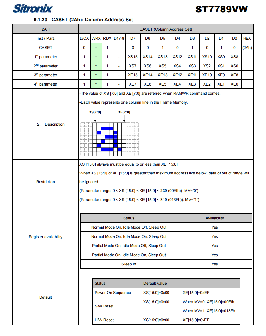
st7789中的坐标地址是16位的,发送起始地址和终止地址时我们需要分为两字节分两次发送,先发高八位后发第八位。总共需要发4组数据(还有行地址)
具体流程图:
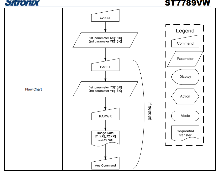
可以看见和代码的顺序是一致的,先设置起始列和终止列,再设置起始行和终止行,最后写RAM指令,后续直接接数据。而写入显存的16位数据会在TFT屏幕上直接显现出物理的颜色。
小小总结一下:操作逻辑大致如下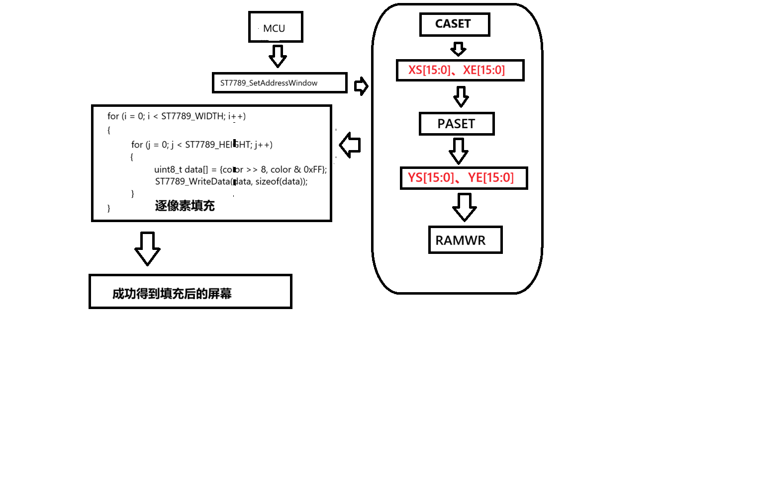
下面是一些具体的绘画函数介绍,大致逻辑和上面一样。
画点(像素)函数:
void ST7789_DrawPixel(uint16_t x, uint16_t y, uint16_t color)
{
	if ((x < 0) || (x >= ST7789_WIDTH) ||
		 (y < 0) || (y >= ST7789_HEIGHT))	return;

	ST7789_SetAddressWindow(x, y, x, y);
	uint8_t data[] = {color >> 8, color & 0xFF};
	ST7789_Select();
	ST7789_WriteData(data, sizeof(data));
	ST7789_UnSelect();
}
因为我们是一字节一字节的发送,所以需要把颜色的数据分为两个字节发送。st7789在接收到我们发送的这两个连续的字节后会自己将其拼接成16位的RGB565数据,并显示在显存里。
画线条函数:
void ST7789_DrawLine(uint16_t x0, uint16_t y0, uint16_t x1, uint16_t y1,
        uint16_t color) {
	uint16_t swap;
    uint16_t steep = ABS(y1 - y0) > ABS(x1 - x0);
    if (steep) {
		swap = x0;
		x0 = y0;
		y0 = swap;

		swap = x1;
		x1 = y1;
		y1 = swap;
        //_swap_int16_t(x0, y0);
        //_swap_int16_t(x1, y1);
    }

    if (x0 > x1) {
		swap = x0;
		x0 = x1;
		x1 = swap;

		swap = y0;
		y0 = y1;
		y1 = swap;
        //_swap_int16_t(x0, x1);
        //_swap_int16_t(y0, y1);
    }

    int16_t dx, dy;
    dx = x1 - x0;
    dy = ABS(y1 - y0);

    int16_t err = dx / 2;
    int16_t ystep;

    if (y0 < y1) {
        ystep = 1;
    } else {
        ystep = -1;
    }

    for (; x0<=x1; x0++) {
        if (steep) {
            ST7789_DrawPixel(y0, x0, color);
        } else {
            ST7789_DrawPixel(x0, y0, color);
        }
        err -= dy;
        if (err < 0) {
            y0 += ystep;
            err += dx;
        }
    }
}
这里采用的是布雷森汉姆直线算法,具体可以移步至其他博客了解学习。
备注:这里的err和dy其实就是1/2(中点)和1经过这条直线等比增长的
画矩形函数:
void ST7789_DrawRectangle(uint16_t x1, uint16_t y1, uint16_t x2, uint16_t y2, uint16_t color)
{
	ST7789_Select();
	ST7789_DrawLine(x1, y1, x2, y1, color);
	ST7789_DrawLine(x1, y1, x1, y2, color);
	ST7789_DrawLine(x1, y2, x2, y2, color);
	ST7789_DrawLine(x2, y1, x2, y2, color);
	ST7789_UnSelect();
}
这个函数简单,不多说。
画圆函数:
void ST7789_DrawCircle(uint16_t x0, uint16_t y0, uint8_t r, uint16_t color)
{
	int16_t f = 1 - r;
	int16_t ddF_x = 1;
	int16_t ddF_y = -2 * r;
	int16_t x = 0;
	int16_t y = r;

	ST7789_Select();
	ST7789_DrawPixel(x0, y0 + r, color);
	ST7789_DrawPixel(x0, y0 - r, color);
	ST7789_DrawPixel(x0 + r, y0, color);
	ST7789_DrawPixel(x0 - r, y0, color);

	while (x < y) {
		if (f >= 0) {
			y--;
			ddF_y += 2;
			f += ddF_y;
		}
		x++;
		ddF_x += 2;
		f += ddF_x;

		ST7789_DrawPixel(x0 + x, y0 + y, color);
		ST7789_DrawPixel(x0 - x, y0 + y, color);
		ST7789_DrawPixel(x0 + x, y0 - y, color);
		ST7789_DrawPixel(x0 - x, y0 - y, color);

		ST7789_DrawPixel(x0 + y, y0 + x, color);
		ST7789_DrawPixel(x0 - y, y0 + x, color);
		ST7789_DrawPixel(x0 + y, y0 - x, color);
		ST7789_DrawPixel(x0 - y, y0 - x, color);
	}
	ST7789_UnSelect();
}
显示图片函数:
void ST7789_DrawImage(uint16_t x, uint16_t y, uint16_t w, uint16_t h, const uint16_t *data)
{
	if ((x >= ST7789_WIDTH) || (y >= ST7789_HEIGHT))
		return;
	if ((x + w - 1) >= ST7789_WIDTH)
		return;
	if ((y + h - 1) >= ST7789_HEIGHT)
		return;

	ST7789_Select();
	ST7789_SetAddressWindow(x, y, x + w - 1, y + h - 1);
	ST7789_WriteData((uint8_t *)data, sizeof(uint16_t) * w * h);
	ST7789_UnSelect();
}
可以在字库里开辟一块地来提前存储需要的图片数组(但是MCU的flash内存很可能不够,需要其他的存储模块)。
后面还有一些函数大同小异,可以自己研究。
三、初始化和数据手册深挖
1.st7789的颜色显示选择
我们一般选用的是RGB565格式的16位数据来显示(因为人眼对绿色更敏感)即:
[RRRRRGGG][GGGBBBBB]如果要显示一个RGB(255,0,0)的像素点,它应该是0xF800。
查找数据手册,找到如下内容:
因为我们要选择65K的RGB接口和16位的格式所以应该给st7789传送0x55的数据
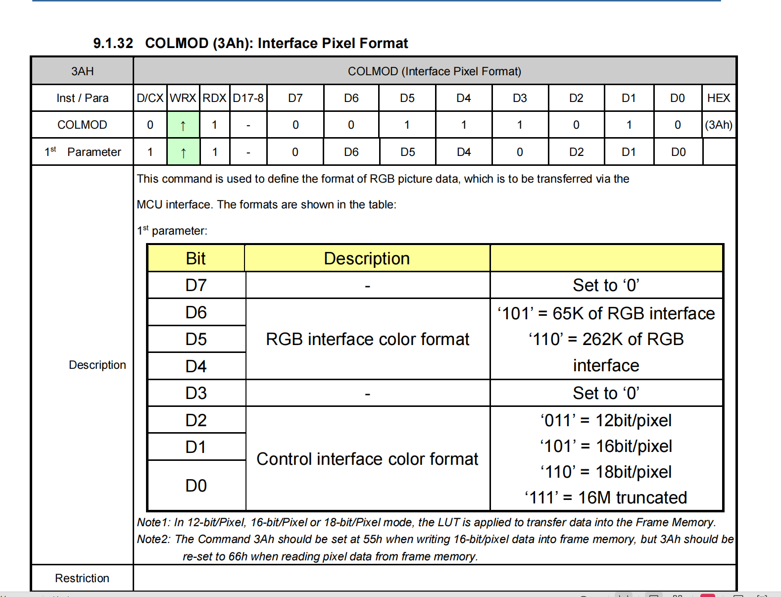
具体代码:
ST7789_WriteCommand(ST7789_COLMOD);		//	Set color mode
ST7789_WriteSmallData(ST7789_COLOR_MODE_16bit);2.MADCTL
MADCTL是显存数据访问控制,这里默认全为0即可。它是控制在屏幕上的显示方向的以及是否旋转图像(如从左到右,从上到下这类设置)。 如有其他的需要再具体去查各个数据的意义。
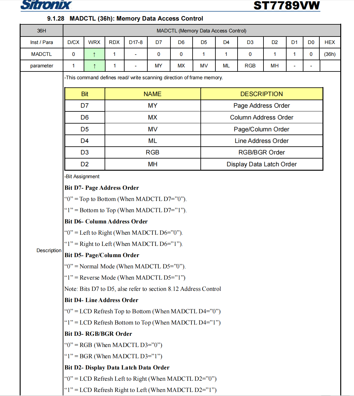
代码:(这里我们先对其进行初始化恢复安全值)
ST7789_WriteCommand(ST7789_MADCTL);
ST7789_WriteSmallData(0x00);
后面会在进行一次设置:
ST7789_SetRotation(ST7789_ROTATION); // MADCTL (Display Rotation)3.PORCH CTL
这个指令设置屏幕显示时序中的 “消隐期(Porch)”,避免画面闪烁或撕裂
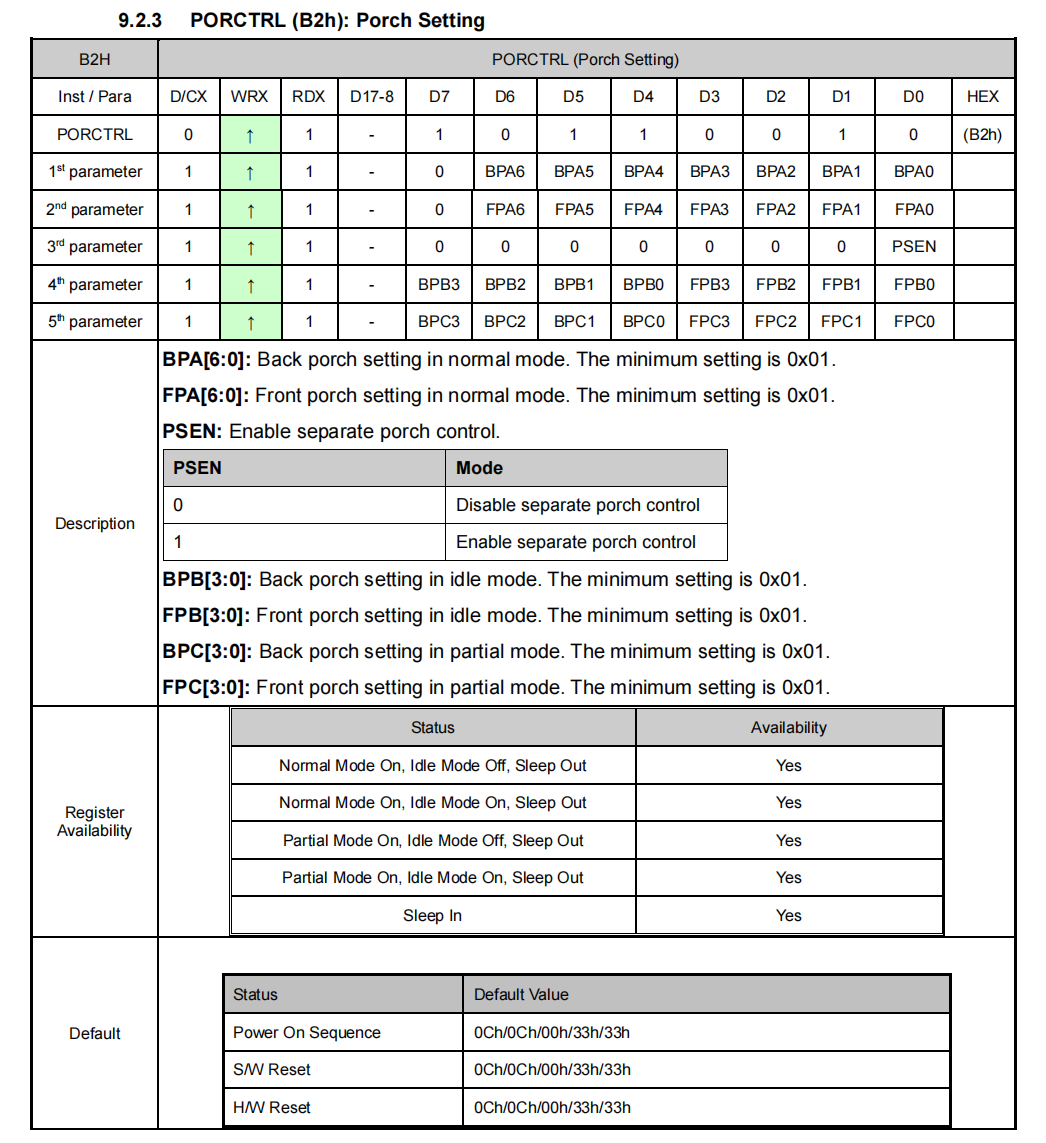
0x0C:Normal 模式的Back Porch(后消隐期)设置为 0x0C;0x0C:Normal 模式的Front Porch(前消隐期)设置为 0x0C;0x00:禁用独立 Porch 控制(PSEN=0),低功耗模式复用 Normal 模式的 Porch 参数;0x33:Idle 模式的 Back Porch(BPB[3:0]=0x3)和 Front Porch(FPB[3:0]=0x3)设置为 0x3;0x33:Partial 模式的 Back Porch(BPC[3:0]=0x3)和 Front Porch(FPC[3:0]=0x3)设置为 0x3。
这个参数主包不是很懂,这些好像都是默认配置。
4.st7789的一些电压电源配置
	/* Internal LCD Voltage generator settings */
    ST7789_WriteCommand(0XB7);				//	Gate Control
    ST7789_WriteSmallData(0x35);			//	Default value
    ST7789_WriteCommand(0xBB);				//	VCOM setting
    ST7789_WriteSmallData(0x19);			//	0.725v (default 0.75v for 0x20)
    ST7789_WriteCommand(0xC0);				//	LCMCTRL
    ST7789_WriteSmallData (0x2C);			//	Default value
    ST7789_WriteCommand (0xC2);				//	VDV and VRH command Enable
    ST7789_WriteSmallData (0x01);			//	Default value
    ST7789_WriteCommand (0xC3);				//	VRH set
    ST7789_WriteSmallData (0x12);			//	+-4.45v (defalut +-4.1v for 0x0B)
    ST7789_WriteCommand (0xC4);				//	VDV set
    ST7789_WriteSmallData (0x20);			//	Default value
    ST7789_WriteCommand (0xC6);				//	Frame rate control in normal mode
    ST7789_WriteSmallData (0x0F);			//	Default value (60HZ)
    ST7789_WriteCommand (0xD0);				//	Power control
    ST7789_WriteSmallData (0xA4);			//	Default value
    ST7789_WriteSmallData (0xA1);			//	Default value
具体有什么作用可以具体去查手册。
5.最后的配置
指令0xE0和0xE1分别是正向伽马调整和反向伽马调整,作用分别是调整亮部区域和暗部区域的亮度非线性响应,让画面的明暗过渡更符合人眼视觉特性。具体参数可以依据大众的经验和厂家给出的数据。
下面的指令的作用按顺序分别是开启反色(有些模组务必要开启),结除睡眠模式,开启正常显示模式(退出低功耗模式),开启主屏幕。这些指令都没有参数,发送指令即可。
ST7789_WriteCommand(0xE0);
	{
		uint8_t data[] = {0xD0, 0x04, 0x0D, 0x11, 0x13, 0x2B, 0x3F, 0x54, 0x4C, 0x18, 0x0D, 0x0B, 0x1F, 0x23};
		ST7789_WriteData(data, sizeof(data));
	}

    ST7789_WriteCommand(0xE1);
	{
		uint8_t data[] = {0xD0, 0x04, 0x0C, 0x11, 0x13, 0x2C, 0x3F, 0x44, 0x51, 0x2F, 0x1F, 0x1F, 0x20, 0x23};
		ST7789_WriteData(data, sizeof(data));
	}
    ST7789_WriteCommand (ST7789_INVON);		//	Inversion ON
	ST7789_WriteCommand (ST7789_SLPOUT);	//	Out of sleep mode
  	ST7789_WriteCommand (ST7789_NORON);		//	Normal Display on
  	ST7789_WriteCommand (ST7789_DISPON);	//	Main screen turned on

	HAL_Delay(50);
	ST7789_Fill_Color(BLACK);				//	Fill with Black.
初始化总代码:
void ST7789_Init(void)
{
	#ifdef USE_DMA
		memset(disp_buf, 0, sizeof(disp_buf));
	#endif
	HAL_Delay(10);
    ST7789_RST_Clr();
    HAL_Delay(10);
    ST7789_RST_Set();
    HAL_Delay(20);

	ST7789_WriteCommand(ST7789_MADCTL);		//	Set color mode
	ST7789_WriteSmallData(0x00);
    ST7789_WriteCommand(ST7789_COLMOD);		//	Set color mode
    ST7789_WriteSmallData(ST7789_COLOR_MODE_16bit);
  	ST7789_WriteCommand(0xB2);				//	Porch control
	{
		uint8_t data[] = {0x0C, 0x0C, 0x00, 0x33, 0x33};
		ST7789_WriteData(data, sizeof(data));
	}
	ST7789_SetRotation(ST7789_ROTATION);	//	MADCTL (Display Rotation)

	/* Internal LCD Voltage generator settings */
    ST7789_WriteCommand(0XB7);				//	Gate Control
    ST7789_WriteSmallData(0x35);			//	Default value
    ST7789_WriteCommand(0xBB);				//	VCOM setting
    ST7789_WriteSmallData(0x19);			//	0.725v (default 0.75v for 0x20)
    ST7789_WriteCommand(0xC0);				//	LCMCTRL
    ST7789_WriteSmallData (0x2C);			//	Default value
    ST7789_WriteCommand (0xC2);				//	VDV and VRH command Enable
    ST7789_WriteSmallData (0x01);			//	Default value
    ST7789_WriteCommand (0xC3);				//	VRH set
    ST7789_WriteSmallData (0x12);			//	+-4.45v (defalut +-4.1v for 0x0B)
    ST7789_WriteCommand (0xC4);				//	VDV set
    ST7789_WriteSmallData (0x20);			//	Default value
    ST7789_WriteCommand (0xC6);				//	Frame rate control in normal mode
    ST7789_WriteSmallData (0x0F);			//	Default value (60HZ)
    ST7789_WriteCommand (0xD0);				//	Power control
    ST7789_WriteSmallData (0xA4);			//	Default value
    ST7789_WriteSmallData (0xA1);			//	Default value
	/**************** Division line ****************/

	ST7789_WriteCommand(0xE0);
	{
		uint8_t data[] = {0xD0, 0x04, 0x0D, 0x11, 0x13, 0x2B, 0x3F, 0x54, 0x4C, 0x18, 0x0D, 0x0B, 0x1F, 0x23};
		ST7789_WriteData(data, sizeof(data));
	}

    ST7789_WriteCommand(0xE1);
	{
		uint8_t data[] = {0xD0, 0x04, 0x0C, 0x11, 0x13, 0x2C, 0x3F, 0x44, 0x51, 0x2F, 0x1F, 0x1F, 0x20, 0x23};
		ST7789_WriteData(data, sizeof(data));
	}
    ST7789_WriteCommand (ST7789_INVON);		//	Inversion ON
	ST7789_WriteCommand (ST7789_SLPOUT);	//	Out of sleep mode
  	ST7789_WriteCommand (ST7789_NORON);		//	Normal Display on
  	ST7789_WriteCommand (ST7789_DISPON);	//	Main screen turned on

	HAL_Delay(50);
	ST7789_Fill_Color(BLACK);				//	Fill with Black.
}
我去,终于写完,就差不多这样吧。主包好累

北京人形旗下天工造物具身智能开源社区,聚焦具身天工与慧思开物两大平台
更多推荐
 22
22 0
0- 0


 已为社区贡献3条内容

所有评论(0)