基于Protues8.15+stm32f103c8t6按键驱动
·
目录
话不多说直接上代码
代码
/*
stm32全接按键测试模板
*/


#include "stm32f10x.h"                  // Device header


u8 led_flag=0;

/**
  * @brief  微秒级延时
  * @param  xus 延时时长,范围:0~233015
  * @retval 无
  */
void Delay_us(uint32_t xus)
{
	SysTick->LOAD = 72 * xus;				//设置定时器重装值
	SysTick->VAL = 0x00;					//清空当前计数值
	SysTick->CTRL = 0x00000005;				//设置时钟源为HCLK,启动定时器
	while(!(SysTick->CTRL & 0x00010000));	//等待计数到0
	SysTick->CTRL = 0x00000004;				//关闭定时器
}

/**
  * @brief  毫秒级延时
  * @param  xms 延时时长,范围:0~4294967295
  * @retval 无
  */
void Delay_ms(uint32_t xms)
{
	while(xms--)
	{
		Delay_us(1000);
	}
}


void  led_init()
{
	//1.先开启GPIOC外设时钟
	RCC_APB2PeriphClockCmd(RCC_APB2Periph_GPIOC,ENABLE);
	//定义结构体
	//2.设置外设工作模式,分析,根据pc13的电路分析,得出需要将gpioc的13号引脚设置成开漏输出模式,输出速率不需要太高,20MHZ够用
	GPIO_InitTypeDef GPIO_Init_Struct;
	//赋值
	GPIO_Init_Struct.GPIO_Mode = GPIO_Mode_Out_OD ;//使用开漏输出,因为pc13接的是vcc
	GPIO_Init_Struct.GPIO_Pin = GPIO_Pin_13;
	GPIO_Init_Struct.GPIO_Speed = GPIO_Speed_2MHz;
	GPIO_Init(GPIOC, &GPIO_Init_Struct);
	GPIO_SetBits(GPIOC,GPIO_Pin_13);
}

void GPIO_init(GPIO_TypeDef* GPIOx,uint16_t Key_GPIO)
{
	if(GPIOx==GPIOA)
	{
			GPIO_InitTypeDef GPIO_InitStructure;

			RCC_APB2PeriphClockCmd(RCC_APB2Periph_GPIOA, ENABLE);

			GPIO_InitStructure.GPIO_Pin =Key_GPIO;

			GPIO_InitStructure.GPIO_Mode = GPIO_Mode_IPU;

			GPIO_InitStructure.GPIO_Speed = GPIO_Speed_50MHz;

			/*调用库函数,初始化GPIO*/
			GPIO_Init(GPIOA, &GPIO_InitStructure);
	}

	if(GPIOx==GPIOB)
	{
			GPIO_InitTypeDef GPIO_InitStructure;

			RCC_APB2PeriphClockCmd(RCC_APB2Periph_GPIOB, ENABLE);

			GPIO_InitStructure.GPIO_Pin =Key_GPIO;

			GPIO_InitStructure.GPIO_Mode = GPIO_Mode_IPU;

			GPIO_InitStructure.GPIO_Speed = GPIO_Speed_50MHz;

			/*调用库函数,初始化GPIO*/
			GPIO_Init(GPIOB, &GPIO_InitStructure);
	}

}


uint8_t get_flag(void){

	uint8_t KeyNum = 0;
	if(GPIO_ReadInputDataBit(GPIOA , GPIO_Pin_0)==0){
		Delay_ms(20);
		while(GPIO_ReadInputDataBit(GPIOA , GPIO_Pin_0)==0);
		Delay_ms(20);
		KeyNum=1;
	}
	if(GPIO_ReadInputDataBit(GPIOA , GPIO_Pin_1)==0){
		Delay_ms(20);
		while(GPIO_ReadInputDataBit(GPIOA , GPIO_Pin_1)==0);
		Delay_ms(20);
		KeyNum=2;
	}
	if(GPIO_ReadInputDataBit(GPIOA , GPIO_Pin_2)==0){
		Delay_ms(20);
		while(GPIO_ReadInputDataBit(GPIOA , GPIO_Pin_2)==0);
		Delay_ms(20);
		KeyNum=3;
	}
		if(GPIO_ReadInputDataBit(GPIOA , GPIO_Pin_3)==0){
		Delay_ms(20);
		while(GPIO_ReadInputDataBit(GPIOA , GPIO_Pin_3)==0);
		Delay_ms(20);
		KeyNum=4;
	}

		if(GPIO_ReadInputDataBit(GPIOA , GPIO_Pin_4)==0){
		Delay_ms(20);
		while(GPIO_ReadInputDataBit(GPIOA , GPIO_Pin_4)==0);
		Delay_ms(20);
		KeyNum=5;
	}
	if(GPIO_ReadInputDataBit(GPIOA , GPIO_Pin_5)==0){
		Delay_ms(20);
		while(GPIO_ReadInputDataBit(GPIOA , GPIO_Pin_5)==0);
		Delay_ms(20);
		KeyNum=6;
	}
	if(GPIO_ReadInputDataBit(GPIOA , GPIO_Pin_6)==0){
		Delay_ms(20);
		while(GPIO_ReadInputDataBit(GPIOA , GPIO_Pin_6)==0);
		Delay_ms(20);
		KeyNum=7;
	}
	if(GPIO_ReadInputDataBit(GPIOA , GPIO_Pin_7)==0){
		Delay_ms(20);
		while(GPIO_ReadInputDataBit(GPIOA , GPIO_Pin_7)==0);
		Delay_ms(20);
		KeyNum=8;
	}
	if(GPIO_ReadInputDataBit(GPIOA , GPIO_Pin_8)==0){
		Delay_ms(20);
		while(GPIO_ReadInputDataBit(GPIOA , GPIO_Pin_8)==0);
		Delay_ms(20);
		KeyNum=9;
	}
		if(GPIO_ReadInputDataBit(GPIOA , GPIO_Pin_9)==0){
		Delay_ms(20);
		while(GPIO_ReadInputDataBit(GPIOA , GPIO_Pin_9)==0);
		Delay_ms(20);
		KeyNum=10;
	}

		if(GPIO_ReadInputDataBit(GPIOA , GPIO_Pin_10)==0){
		Delay_ms(20);
		while(GPIO_ReadInputDataBit(GPIOA , GPIO_Pin_10)==0);
		Delay_ms(20);
		KeyNum=11;
	}
	if(GPIO_ReadInputDataBit(GPIOA , GPIO_Pin_11)==0){
		Delay_ms(20);
		while(GPIO_ReadInputDataBit(GPIOA , GPIO_Pin_11)==0);
		Delay_ms(20);
		KeyNum=12;
	}
	if(GPIO_ReadInputDataBit(GPIOA , GPIO_Pin_12)==0){
		Delay_ms(20);
		while(GPIO_ReadInputDataBit(GPIOA , GPIO_Pin_12)==0);
		Delay_ms(20);
		KeyNum=13;
	}
		if(GPIO_ReadInputDataBit(GPIOA , GPIO_Pin_13)==0){
		Delay_ms(20);
		while(GPIO_ReadInputDataBit(GPIOA , GPIO_Pin_13)==0);
		Delay_ms(20);
		KeyNum=14;
	}

		if(GPIO_ReadInputDataBit(GPIOA , GPIO_Pin_14)==0){
		Delay_ms(20);
		while(GPIO_ReadInputDataBit(GPIOA , GPIO_Pin_14)==0);
		Delay_ms(20);
		KeyNum=15;
	}
	if(GPIO_ReadInputDataBit(GPIOA , GPIO_Pin_15)==0){
		Delay_ms(20);
		while(GPIO_ReadInputDataBit(GPIOA , GPIO_Pin_15)==0);
		Delay_ms(20);
		KeyNum=16;
	}
//-----------------------PB------------------------------
	if(GPIO_ReadInputDataBit(GPIOB , GPIO_Pin_0)==0){
		Delay_ms(20);
		while(GPIO_ReadInputDataBit(GPIOB , GPIO_Pin_0)==0);
		Delay_ms(20);
		KeyNum=1;
	}
	if(GPIO_ReadInputDataBit(GPIOB , GPIO_Pin_1)==0){
		Delay_ms(20);
		while(GPIO_ReadInputDataBit(GPIOB, GPIO_Pin_1)==0);
		Delay_ms(20);
		KeyNum=2;
	}
	if(GPIO_ReadInputDataBit(GPIOB , GPIO_Pin_2)==0){
		Delay_ms(20);
		while(GPIO_ReadInputDataBit(GPIOB , GPIO_Pin_2)==0);
		Delay_ms(20);
		KeyNum=3;
	}
		if(GPIO_ReadInputDataBit(GPIOB , GPIO_Pin_3)==0){
		Delay_ms(20);
		while(GPIO_ReadInputDataBit(GPIOB , GPIO_Pin_3)==0);
		Delay_ms(20);
		KeyNum=4;
	}

		if(GPIO_ReadInputDataBit(GPIOB , GPIO_Pin_4)==0){
		Delay_ms(20);
		while(GPIO_ReadInputDataBit(GPIOB , GPIO_Pin_4)==0);
		Delay_ms(20);
		KeyNum=5;
	}
	if(GPIO_ReadInputDataBit(GPIOB , GPIO_Pin_5)==0){
		Delay_ms(20);
		while(GPIO_ReadInputDataBit(GPIOB , GPIO_Pin_5)==0);
		Delay_ms(20);
		KeyNum=6;
	}
	if(GPIO_ReadInputDataBit(GPIOB , GPIO_Pin_6)==0){
		Delay_ms(20);
		while(GPIO_ReadInputDataBit(GPIOB , GPIO_Pin_6)==0);
		Delay_ms(20);
		KeyNum=7;
	}
	if(GPIO_ReadInputDataBit(GPIOB , GPIO_Pin_7)==0){
		Delay_ms(20);
		while(GPIO_ReadInputDataBit(GPIOB , GPIO_Pin_7)==0);
		Delay_ms(20);
		KeyNum=8;
	}
	if(GPIO_ReadInputDataBit(GPIOB , GPIO_Pin_8)==0){
		Delay_ms(20);
		while(GPIO_ReadInputDataBit(GPIOB , GPIO_Pin_8)==0);
		Delay_ms(20);
		KeyNum=9;
	}
		if(GPIO_ReadInputDataBit(GPIOB , GPIO_Pin_9)==0){
		Delay_ms(20);
		while(GPIO_ReadInputDataBit(GPIOB , GPIO_Pin_9)==0);
		Delay_ms(20);
		KeyNum=10;
	}

		if(GPIO_ReadInputDataBit(GPIOB , GPIO_Pin_10)==0){
		Delay_ms(20);
		while(GPIO_ReadInputDataBit(GPIOB , GPIO_Pin_10)==0);
		Delay_ms(20);
		KeyNum=11;
	}
	if(GPIO_ReadInputDataBit(GPIOB , GPIO_Pin_11)==0){
		Delay_ms(20);
		while(GPIO_ReadInputDataBit(GPIOB , GPIO_Pin_11)==0);
		Delay_ms(20);
		KeyNum=12;
	}
	if(GPIO_ReadInputDataBit(GPIOB , GPIO_Pin_12)==0){
		Delay_ms(20);
		while(GPIO_ReadInputDataBit(GPIOB , GPIO_Pin_12)==0);
		Delay_ms(20);
		KeyNum=13;
	}
		if(GPIO_ReadInputDataBit(GPIOB , GPIO_Pin_13)==0){
		Delay_ms(20);
		while(GPIO_ReadInputDataBit(GPIOB , GPIO_Pin_13)==0);
		Delay_ms(20);
		KeyNum=14;
	}

		if(GPIO_ReadInputDataBit(GPIOB , GPIO_Pin_14)==0){
		Delay_ms(20);
		while(GPIO_ReadInputDataBit(GPIOB , GPIO_Pin_14)==0);
		Delay_ms(20);
		KeyNum=15;
	}
	if(GPIO_ReadInputDataBit(GPIOB , GPIO_Pin_15)==0){
		Delay_ms(20);
		while(GPIO_ReadInputDataBit(GPIOB , GPIO_Pin_15)==0);
		Delay_ms(20);
		KeyNum=16;
	}

	return KeyNum;

}

int flag;

void flash_led(void)//led闪烁
{
		GPIO_ResetBits(GPIOC,GPIO_Pin_13);//setbits是写1,resetbits是写0
		Delay_ms(100*flag);
		GPIO_SetBits(GPIOC,GPIO_Pin_13);
}


void flag_change()
{
		switch(flag)
		{
			case 1:flash_led();//led闪烁
			break;
			case 2:flash_led();
			break;
			case 3:flash_led();
			break;
			case 4:flash_led();
			break;
			case 5:flash_led();
			break;
			case 6:flash_led();
			break;
			case 7:flash_led();
			break;
			case 8:flash_led();
			break;
			case 9:flash_led();
			break;
			case 10:flash_led();
			break;
			case 11:flash_led();//led闪烁
			break;
			case 12:flash_led();
			break;
			case 13:flash_led();
			break;
			case 14:flash_led();
			break;
			case 15:flash_led();
			break;
			case 16:flash_led();
			default:break;

		}
}


int main(void){
		led_init();
		GPIO_init(GPIOA,GPIO_Pin_All);
		GPIO_init(GPIOB,GPIO_Pin_All);
		Delay_ms(1000);

	//3.控制引脚高低电平。将pc13点亮,即数据输出寄存器写0,引脚输出低电平,led亮,写1,引脚高阻态,led灭

		while(1)
		{
			flag=get_flag();
			flag_change();
		}
}
如果需要高电平将上面的判定条件将0改为1即可。
仿真电路如下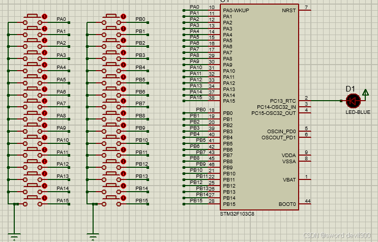
仿真效果
202503261353
该系统功能为PA、PB全端口按键低电平触发PC13led点亮不同时间,不建议使用上面仿真的测试电路进行电路设计,因为单片机的带负载能力有限,容易出现硬件故障,适用于需要低电平触发的系统,可以外部利用lm393比较电路去实现输出高低电平然后配合该驱动使用。
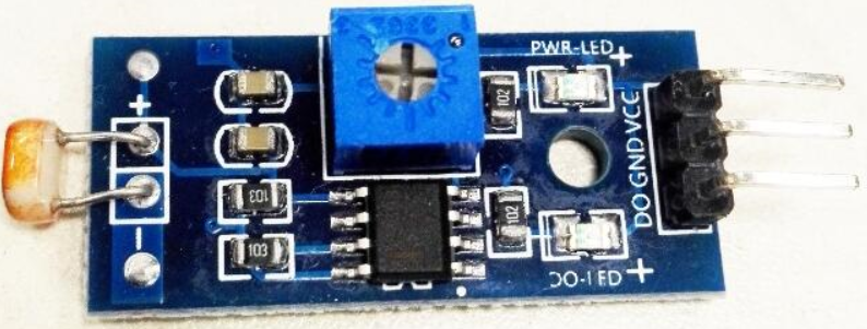
常见应用LM393的模块
震动传感器、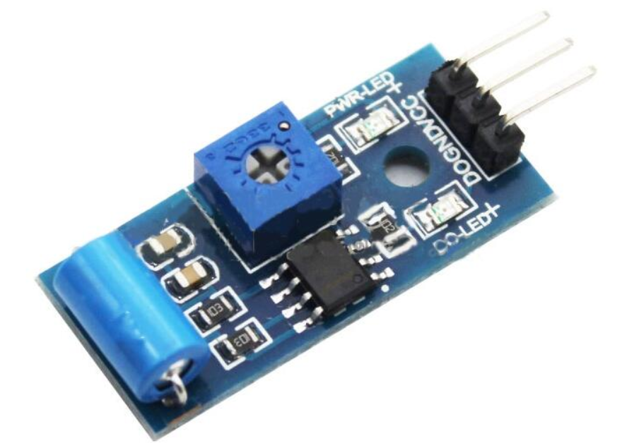 光电传感器,
红外传感器,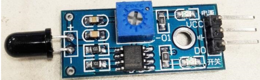 声音传感器,
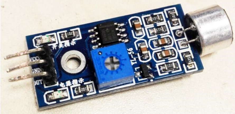
全系列烟雾传感器,土壤湿度传感器,磁通传感器等。
定时器实现精准延时
有人已经做了,便不再赘述。
基本定时器TIM6实现精确延时 - 一蓑烟雨任平生&wf - 博客园
模拟iic驱动OLED显示按键
暂时未写完
/*
stm32OLED显示接按键
*/


#include "stm32f10x.h"                  // Device header


u8 led_flag=0;

/**
  * @brief  微秒级延时
  * @param  xus 延时时长,范围:0~233015
  * @retval 无
  */
void Delay_us(uint32_t xus)
{
	SysTick->LOAD = 72 * xus;				//设置定时器重装值
	SysTick->VAL = 0x00;					//清空当前计数值
	SysTick->CTRL = 0x00000005;				//设置时钟源为HCLK,启动定时器
	while(!(SysTick->CTRL & 0x00010000));	//等待计数到0
	SysTick->CTRL = 0x00000004;				//关闭定时器
}

/**
  * @brief  毫秒级延时
  * @param  xms 延时时长,范围:0~4294967295
  * @retval 无
  */
void Delay_ms(uint32_t xms)
{
	while(xms--)
	{
		Delay_us(1000);
	}
}


void  led_init()
{
	//1.先开启GPIOC外设时钟
	RCC_APB2PeriphClockCmd(RCC_APB2Periph_GPIOC,ENABLE);
	//定义结构体
	//2.设置外设工作模式,分析,根据pc13的电路分析,得出需要将gpioc的13号引脚设置成开漏输出模式,输出速率不需要太高,20MHZ够用
	GPIO_InitTypeDef GPIO_Init_Struct;
	//赋值
	GPIO_Init_Struct.GPIO_Mode = GPIO_Mode_Out_OD ;//使用开漏输出,因为pc13接的是vcc
	GPIO_Init_Struct.GPIO_Pin = GPIO_Pin_13;
	GPIO_Init_Struct.GPIO_Speed = GPIO_Speed_2MHz;
	GPIO_Init(GPIOC, &GPIO_Init_Struct);
	GPIO_SetBits(GPIOC,GPIO_Pin_13);
}

void GPIO_init(GPIO_TypeDef* GPIOx,uint16_t Key_GPIO)
{
	if(GPIOx==GPIOA)
	{
			GPIO_InitTypeDef GPIO_InitStructure;

			RCC_APB2PeriphClockCmd(RCC_APB2Periph_GPIOA, ENABLE);

			GPIO_InitStructure.GPIO_Pin =Key_GPIO;

			GPIO_InitStructure.GPIO_Mode = GPIO_Mode_IPU;

			GPIO_InitStructure.GPIO_Speed = GPIO_Speed_50MHz;

			/*调用库函数,初始化GPIO*/
			GPIO_Init(GPIOA, &GPIO_InitStructure);
	}

	if(GPIOx==GPIOB)
	{
			GPIO_InitTypeDef GPIO_InitStructure;

			RCC_APB2PeriphClockCmd(RCC_APB2Periph_GPIOB, ENABLE);

			GPIO_InitStructure.GPIO_Pin =Key_GPIO;

			GPIO_InitStructure.GPIO_Mode = GPIO_Mode_IPU;

			GPIO_InitStructure.GPIO_Speed = GPIO_Speed_50MHz;

			/*调用库函数,初始化GPIO*/
			GPIO_Init(GPIOB, &GPIO_InitStructure);
	}

}


uint8_t get_flag(GPIO_TypeDef* GPIOx){

	uint8_t KeyNum = 0;
	if(GPIO_ReadInputDataBit(GPIOx, GPIO_Pin_0)==0){
		Delay_ms(20);
		while(GPIO_ReadInputDataBit(GPIOx, GPIO_Pin_0)==0);
		Delay_ms(20);
		KeyNum=1;
	}
	if(GPIO_ReadInputDataBit(GPIOx, GPIO_Pin_1)==0){
		Delay_ms(20);
		while(GPIO_ReadInputDataBit(GPIOx, GPIO_Pin_1)==0);
		Delay_ms(20);
		KeyNum=2;
	}
	if(GPIO_ReadInputDataBit(GPIOx, GPIO_Pin_2)==0){
		Delay_ms(20);
		while(GPIO_ReadInputDataBit(GPIOx, GPIO_Pin_2)==0);
		Delay_ms(20);
		KeyNum=3;
	}
		if(GPIO_ReadInputDataBit(GPIOx, GPIO_Pin_3)==0){
		Delay_ms(20);
		while(GPIO_ReadInputDataBit(GPIOx, GPIO_Pin_3)==0);
		Delay_ms(20);
		KeyNum=4;
	}

		if(GPIO_ReadInputDataBit(GPIOx, GPIO_Pin_4)==0){
		Delay_ms(20);
		while(GPIO_ReadInputDataBit(GPIOx, GPIO_Pin_4)==0);
		Delay_ms(20);
		KeyNum=5;
	}
	if(GPIO_ReadInputDataBit(GPIOA , GPIO_Pin_5)==0){
		Delay_ms(20);
		while(GPIO_ReadInputDataBit(GPIOA , GPIO_Pin_5)==0);
		Delay_ms(20);
		KeyNum=6;
	}
	if(GPIO_ReadInputDataBit(GPIOx, GPIO_Pin_6)==0){
		Delay_ms(20);
		while(GPIO_ReadInputDataBit(GPIOx, GPIO_Pin_6)==0);
		Delay_ms(20);
		KeyNum=7;
	}
	if(GPIO_ReadInputDataBit(GPIOx, GPIO_Pin_7)==0){
		Delay_ms(20);
		while(GPIO_ReadInputDataBit(GPIOx, GPIO_Pin_7)==0);
		Delay_ms(20);
		KeyNum=8;
	}
	if(GPIO_ReadInputDataBit(GPIOx, GPIO_Pin_8)==0){
		Delay_ms(20);
		while(GPIO_ReadInputDataBit(GPIOx, GPIO_Pin_8)==0);
		Delay_ms(20);
		KeyNum=9;
	}
		if(GPIO_ReadInputDataBit(GPIOx, GPIO_Pin_9)==0){
		Delay_ms(20);
		while(GPIO_ReadInputDataBit(GPIOx, GPIO_Pin_9)==0);
		Delay_ms(20);
		KeyNum=10;
	}

		if(GPIO_ReadInputDataBit(GPIOx, GPIO_Pin_10)==0){
		Delay_ms(20);
		while(GPIO_ReadInputDataBit(GPIOx, GPIO_Pin_10)==0);
		Delay_ms(20);
		KeyNum=11;
	}
	if(GPIO_ReadInputDataBit(GPIOx, GPIO_Pin_11)==0){
		Delay_ms(20);
		while(GPIO_ReadInputDataBit(GPIOx, GPIO_Pin_11)==0);
		Delay_ms(20);
		KeyNum=12;
	}
	if(GPIO_ReadInputDataBit(GPIOx, GPIO_Pin_12)==0){
		Delay_ms(20);
		while(GPIO_ReadInputDataBit(GPIOx, GPIO_Pin_12)==0);
		Delay_ms(20);
		KeyNum=13;
	}
		if(GPIO_ReadInputDataBit(GPIOx, GPIO_Pin_13)==0){
		Delay_ms(20);
		while(GPIO_ReadInputDataBit(GPIOx, GPIO_Pin_13)==0);
		Delay_ms(20);
		KeyNum=14;
	}

		if(GPIO_ReadInputDataBit(GPIOx, GPIO_Pin_14)==0){
		Delay_ms(20);
		while(GPIO_ReadInputDataBit(GPIOx, GPIO_Pin_14)==0);
		Delay_ms(20);
		KeyNum=15;
	}
	if(GPIO_ReadInputDataBit(GPIOx, GPIO_Pin_15)==0){
		Delay_ms(20);
		while(GPIO_ReadInputDataBit(GPIOA , GPIO_Pin_15)==0);
		Delay_ms(20);
		KeyNum=16;
	}


	return KeyNum-1;

}

int flag,flagA,flagB;

void flash_led(void)//led闪烁
{
		GPIO_ResetBits(GPIOC,GPIO_Pin_13);//setbits是写1,resetbits是写0
		Delay_ms(100);
		GPIO_SetBits(GPIOC,GPIO_Pin_13);
}


void flagA_change()
{
		switch(flagA)
		{
            case 0:flash_led();//led闪烁
			break;
			case 1:flash_led();
			break;
			case 2:flash_led();
			break;
			case 3:flash_led();
			break;
			case 4:flash_led();
			break;
			case 5:flash_led();
			break;
			case 6:flash_led();
			break;
			case 7:flash_led();
			break;
			case 8:flash_led();
			break;
			case 9:flash_led();
			break;
			case 10:flash_led();
			break;
			case 11:flash_led();//led闪烁
			break;
			case 12:flash_led();
			break;
			case 13:flash_led();
			break;
			case 14:flash_led();
			break;
			case 15:flash_led();
			break;
			default:break;

		}
            flag=1;

}

void flagB_change()
{
        switch(flagB)
		{
            case 0:flash_led();//led闪烁
			break;
			case 1:flash_led();
			break;
			case 2:flash_led();
			break;
			case 3:flash_led();
			break;
			case 4:flash_led();
			break;
			case 5:flash_led();
			break;
			case 6:flash_led();
			break;
			case 7:flash_led();
			break;
			case 8:flash_led();
			break;
			case 9:flash_led();
			break;
			case 10:flash_led();
			break;
			case 11:flash_led();//led闪烁
			break;
			case 12:flash_led();
			break;
			case 13:flash_led();
			break;
			case 14:flash_led();
			break;
			case 15:flash_led();
			break;
			default:break;

		}
            flag=0;

}

void OLED_show(void)
{
    if(flag=1);
    if(flag=0);

}

int main(void){
		led_init();
		GPIO_init(GPIOA,GPIO_Pin_All);
		GPIO_init(GPIOB,GPIO_Pin_All);
		Delay_ms(1000);

	//3.控制引脚高低电平。将pc13点亮,即数据输出寄存器写0,引脚输出低电平,led亮,写1,引脚高阻态,led灭

		while(1)
		{
			flagA=get_flag(GPIOA);
            flagB=get_flag(GPIOB);
			flagA_change();
            flagB_change();
		}
}

北京人形旗下天工造物具身智能开源社区,聚焦具身天工与慧思开物两大平台
更多推荐
 8
8 0
0- 0


 已为社区贡献5条内容

所有评论(0)