【嵌入式Linux】嵌入式Linux驱动开发基础知识之Pinctrl子系统和GPIO子系统的使用
文章目录
前言
韦东山嵌入式Linux驱动开发基础知识学习笔记
文章中大多内容来自韦东山老师的文档,还有部分个人根据自己需求补充的内容
视频教程地址:https://www.bilibili.com/video/BV14f4y1Q7ti
上一章中介绍了设备树模型,可以帮助开发者省去在内核中指定资源的步骤,本章介绍Pinctrl子系统和GPIO子系统,使用这两个子系统可帮助让驱动开发者不再需要操作繁琐的GPIO寄存器,直接使用厂商提供的子系统就可以完成GPIO的使用
1、Pinctrl子系统
1.1、为什么有Pinctrl子系统
无论是哪种芯片,都有类似下图的结构:
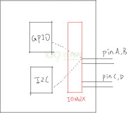
▲引脚可以通过设置IO MUX连接到GPIO或者I2C模块
芯片上的物理引脚可以通过设置IO MUX连接到GPIO或者I2C模块
GPIO、I2C是并列的关系,它们能够使用之前,需要设置IOMUX
有时候并不仅仅是设置IOMUX,还要配些属性,比如上拉、下拉、开漏等等
现在的芯片动辄几百个引脚,在使用到GPIO功能时,让你一个引脚一个引脚去找对应的寄存器,这要疯掉。术业有专攻,这些累活就让芯片厂家做吧──他们是BSP工程师。我们在他们的基础上开发,我们是驱动工程师。开玩笑的,BSP工程师是更懂他自家的芯片,但是如果驱动工程师看不懂他们的代码,那你的进步也有限啊。
所以,要把引脚的复用、配置抽出来,做成Pinctrl子系统,给GPIO、I2C等模块使用。
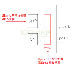
▲Pinctrl子系统和GPIO子系统共同完成GPIO功能
等等,GPIO模块在图中跟I2C不是并列的吗?干嘛在讲Pinctrl时还把GPIO子系统拉进来?
大多数的芯片,没有单独的IOMUX模块,引脚的复用、配置等等,就是在GPIO模块内部实现的。
在硬件上GPIO和Pinctrl是如此密切相关,在软件上它们的关系也非常密切。
1.2、重要的概念
从设备树开始学习Pintrl会比较容易。
这会涉及2个对象:pin controller、client device。
前者提供服务:可以用它来复用引脚、配置引脚。
后者使用服务:声明自己要使用哪些引脚的哪些功能,怎么配置它们。
a. pin controller
在芯片手册里你找不到pin controller,它是一个软件上的概念,你可以认为它对应IOMUX──用来复用引脚,还可以配置引脚(比如上下拉电阻等)。
注意,pin controller和GPIO Controller不是一回事,前者控制的引脚可用于GPIO功能、I2C功能;后者只是把引脚配置为输入、输出等简单的功能。即先用pin controller把引脚配置为GPIO,再用GPIO Controler把引脚配置为输入或输出。
b. client device
“客户设备”,谁的客户?Pinctrl系统的客户,那就是使用Pinctrl系统的设备,使用引脚的设备。它在设备树里会被定义为一个节点,在节点里声明要用哪些引脚。
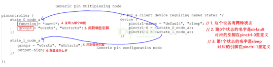
▲pin controller、client device
上图中,左边是pin controller节点,右边是client device节点:
a. pin state:
对于一个“client device”来说,比如对于一个UART设备,它有多个“状态”:default、sleep等,那对应的引脚也有这些状态。
怎么理解?
比如默认状态下,UART设备是工作的,那么所用的引脚就要复用为UART功能。
在休眠状态下,为了省电,可以把这些引脚复用为GPIO功能;或者直接把它们配置输出高电平。
上图中,pinctrl-names里定义了2种状态:default、sleep。
第0种状态用到的引脚在pinctrl-0中定义,它是state_0_node_a,位于pincontroller节点中。
第1种状态用到的引脚在pinctrl-1中定义,它是state_1_node_a,位于pincontroller节点中。
当这个设备处于default状态时,pinctrl子系统会自动根据上述信息把所用引脚复用为uart0功能。
当这这个设备处于sleep状态时,pinctrl子系统会自动根据上述信息把所用引脚配置为高电平。
b. groups和function:
一个设备会用到一个或多个引脚,这些引脚就可以归为一组(group);
这些引脚可以复用为某个功能:function。
当然:一个设备可以用到多组引脚,比如A1、A2两组引脚,A1组复用为F1功能,A2组复用为F2功能。
c. Generic pin multiplexing node和Generic pin configuration node
在上图左边的pin controller节点中,有子节点或孙节点,它们是给client device使用的。
可以用来描述复用信息:哪组(group)引脚复用为哪个功能(function);
可以用来描述配置信息:哪组(group)引脚配置为哪个设置功能(setting),比如上拉、下拉等。
注:pin controller中的节点格式不唯一,更具芯片厂家不同会在命名上格式上出现差异,但是在有差异的表达形式中其内容是一致的
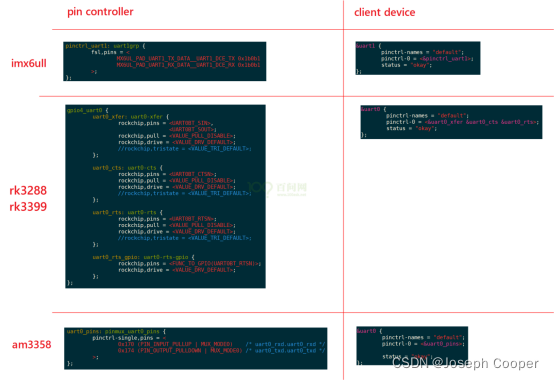
▲pin controller、client devices实例
1.3、代码中怎么引用pinctrl
这是透明的,我们的驱动基本不用管。当设备切换状态时,对应的pinctrl就会被调用。
比如在platform_device和platform_driver的枚举过程中,流程如下:

▲pinctrl在platform_device和platform_driver的枚举过程中被调用
当系统休眠时,也会去设置该设备sleep状态对应的引脚,不需要我们自己去调用代码。
当然也有函数提供给驱动开发者去调用:
devm_pinctrl_get_select_default(struct device *dev);      // 使用"default"状态的引脚
pinctrl_get_select(struct device *dev, const char *name); // 根据name选择某种状态的引脚
pinctrl_put(struct pinctrl *p);   // 不再使用, 退出时调用
2、GPIO子系统
2.1、为什么有GPIO子系统
在Pinctrl子系统将Pin和GPIO模块匹配之后,需要通过GPIO子系统来设定GPIO的输入\输出和读\写,从而达到和之前操作寄存器同样的效果
当BSP工程师实现了GPIO子系统后,我们就可以:
a. 在设备树里指定GPIO引脚
b. 在驱动代码中:
使用GPIO子系统的标准函数获得GPIO、设置GPIO方向、读取/设置GPIO值。
这样的驱动代码,将是单板无关的。
2.2、在设备树中指定GPIO所连接的引脚
在设备树中,“GPIO组”就是一个GPIO Controller,这通常都由芯片厂家设置好。我们要做的是找到它名字,比如“gpio1”,然后指定要用它里面的哪个引脚,比如<&gpio1 0>。
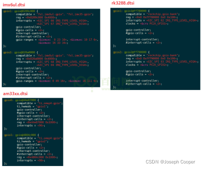
▲不同单板dtsi文件中的GPIO控制器节点
gpio-controller;			//表示这个节点是一个GPIO Controller,它下面有很多引脚。
#gpio-cells = <2>;		//表示这个控制器下每一个引脚要用2个32位的数(cell)来描述。
为什么要用2个数?其实使用多个cell来描述一个引脚,这是GPIO Controller自己决定的。比如可以用其中一个cell来表示那是哪一个引脚,用另一个cell来表示它是高电平有效还是低电平有效,甚至还可以用更多的cell来示其他特性。
普遍的用法是,用第1个cell来表示哪一个引脚,用第2个cell来表示有效电平:
GPIO_ACTIVE_HIGH : 高电平有效
GPIO_ACTIVE_LOW  :  低电平有效
上面的这些信息由芯片厂家负责提供,驱动开发者只需要看懂就行
怎么引用某个引脚呢?
在自己的设备节点中使用属性[<name>-]gpios,示例如下:
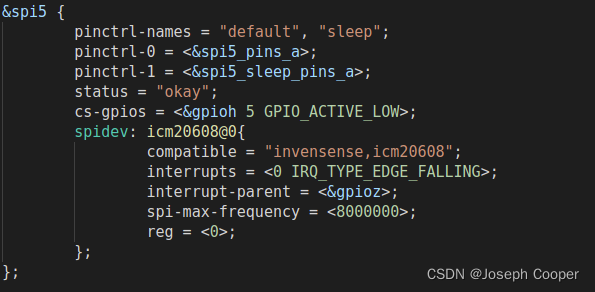
▲STM32MP157 SPI dts
上图中就使用了GPIOH5作为其引脚且将其设定为高电平有效
2.3、在驱动代码中调用GPIO子系统
上面介绍了在设备树中使用GPIO子系统,那么在驱动中要如何使用的GPIO子系统呢?
也就是GPIO子系统的接口函数是什么?
GPIO子系统有两套接口:基于描述符的(descriptor-based)、老的(legacy)。前者的函数都有前缀“gpiod_”,它使用gpio_desc结构体来表示一个引脚;后者的函数都有前缀“gpio_”,它使用一个整数来表示一个引脚。
和GPIO相关的操作包含:get引脚,然后设置方向,读值、写值。
头文件:
#include <linux/gpio/consumer.h>   // descriptor-based
或
#include <linux/gpio.h>            // legacy
下表列出常用的函数:
| descriptor-based | legacy | 说明 |
|---|---|---|
| gpiod_get | gpio_request | 获得GPIO |
| gpiod_get_index | ||
| gpiod_get_array | gpio_request_array | |
| devm_gpiod_get | ||
| devm_gpiod_get_index | ||
| devm_gpiod_get_array | ||
| gpiod_direction_input | gpio_direction_input | 设置方向 |
| gpiod_direction_output | gpio_direction_output | |
| gpiod_get_value | gpio_get_value | 读值、写值 |
| gpiod_set_value | gpio_set_value | |
| gpio_free | gpio_free | 释放GPIO |
| gpiod_put | gpio_free_array | |
| gpiod_put_array | ||
| devm_gpiod_put | ||
| devm_gpiod_put_array |
关于包含devm前缀的函数:
有前缀“devm_”的含义是“设备资源管理”(Managed Device Resource),这是一种自动释放资源的机制。它的思想是“资源是属于设备的,设备不存在时资源就可以自动释放”。
比如在Linux开发过程中,先申请了GPIO,再申请内存;如果内存申请失败,那么在返回之前就需要先释放GPIO资源。如果使用devm的相关函数,在内存申请失败时可以直接返回:设备的销毁函数会自动地释放已经申请了的GPIO资源。
建议使用“devm_”版本的相关函数。
使用举例:
假设设备树中有如下节点
	foo_device {
		compatible = "acme,foo";
		...
		led-gpios = <&gpio 15 GPIO_ACTIVE_HIGH>, /* red */
			    <&gpio 16 GPIO_ACTIVE_HIGH>, /* green */
			    <&gpio 17 GPIO_ACTIVE_HIGH>; /* blue */

		power-gpios = <&gpio 1 GPIO_ACTIVE_LOW>;
	};
在驱动中可以使用一下函数获得引脚
struct gpio_desc *red, *green, *blue, *power;

red = gpiod_get_index(dev, "led", 0, GPIOD_OUT_HIGH);
green = gpiod_get_index(dev, "led", 1, GPIOD_OUT_HIGH);
blue = gpiod_get_index(dev, "led", 2, GPIOD_OUT_HIGH);
power = gpiod_get(dev, "power", GPIOD_OUT_HIGH);
针对gpiod_set_value函数要注意的是,其参数指定的是逻辑值而非物理电平值,其电平高低还取决于其active-low属性
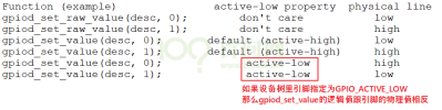
▲gpiod_set_value
旧的“gpio_”函数没办法根据设备树信息获得引脚,它需要先知道引脚号。
引脚号怎么确定?
在GPIO子系统中,每注册一个GPIO Controller时会确定它的“base number”,那么这个控制器里的第n号引脚的号码就是:base number + n。
但是如果硬件有变化、设备树有变化,这个base number并不能保证是固定的,应该查看sysfs来确定base number。
2.4、sysfs中的访问GPIO方法
a. 先确定某个GPIO Controller的基准引脚号(base number),再计算出某个引脚的号码。
比如要找 PG2

▲找到PG2的引脚号码
GPIOG2的引脚号码 = base + 2 = 96 + 2 = 98
可以在下面的设备树文件中找到对应的GPIO信息
stm32mp15xxac-pinctrl.dtsi
// SPDX-License-Identifier: (GPL-2.0+ OR BSD-3-Clause)
/*
 * Copyright (C) STMicroelectronics 2019 - All Rights Reserved
 * Author: Alexandre Torgue <alexandre.torgue@st.com>
 */

&pinctrl {
	st,package = <STM32MP_PKG_AC>;

	gpioa: gpio@50002000 {
		status = "okay";
		ngpios = <16>;
		gpio-ranges = <&pinctrl 0 0 16>;
	};

	gpiob: gpio@50003000 {
		status = "okay";
		ngpios = <16>;
		gpio-ranges = <&pinctrl 0 16 16>;
	};

	gpioc: gpio@50004000 {
		status = "okay";
		ngpios = <16>;
		gpio-ranges = <&pinctrl 0 32 16>;
	};

	gpiod: gpio@50005000 {
		status = "okay";
		ngpios = <16>;
		gpio-ranges = <&pinctrl 0 48 16>;
	};

	gpioe: gpio@50006000 {
		status = "okay";
		ngpios = <16>;
		gpio-ranges = <&pinctrl 0 64 16>;
	};

	gpiof: gpio@50007000 {
		status = "okay";
		ngpios = <16>;
		gpio-ranges = <&pinctrl 0 80 16>;
	};

	gpiog: gpio@50008000 {
		status = "okay";
		ngpios = <16>;
		gpio-ranges = <&pinctrl 0 96 16>;
	};

	gpioh: gpio@50009000 {
		status = "okay";
		ngpios = <16>;
		gpio-ranges = <&pinctrl 0 112 16>;
	};

	gpioi: gpio@5000a000 {
		status = "okay";
		ngpios = <12>;
		gpio-ranges = <&pinctrl 0 128 12>;
	};
};

&pinctrl_z {
	st,package = <STM32MP_PKG_AC>;

	gpioz: gpio@54004000 {
		status = "okay";
		ngpios = <8>;
		gpio-ranges = <&pinctrl_z 0 400 8>;
	};
};
b. 基于sysfs操作引脚:

▲导出PG2节点,设置输入,读取数据,销毁节点
3、基于GPIO子系统的LED驱动程序
3.1、编写思路
- 需要使用Pinctrl子系统将需要配置为GPIO功能的引脚配置为GPIO功能,这只需要在设备树文件中操作
- 需要在驱动中使用到GPIO子系统编写对应的platform_driver,在probe函数中:获得引脚、注册file_operations。在file_operations中:设置方向、读值/写值。
3.2、针对STM32MP157平台编写代码
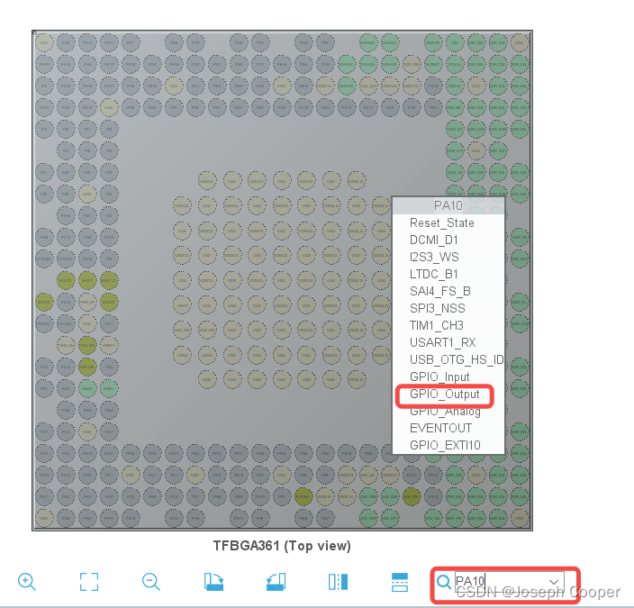
针对STM32MP157D MPU 其厂商ST给出了生成设备树代码的图形化工具STM32CubeMX,按照下图的操作方法可以生成工程文件夹并在其中找到生成的设备树文件
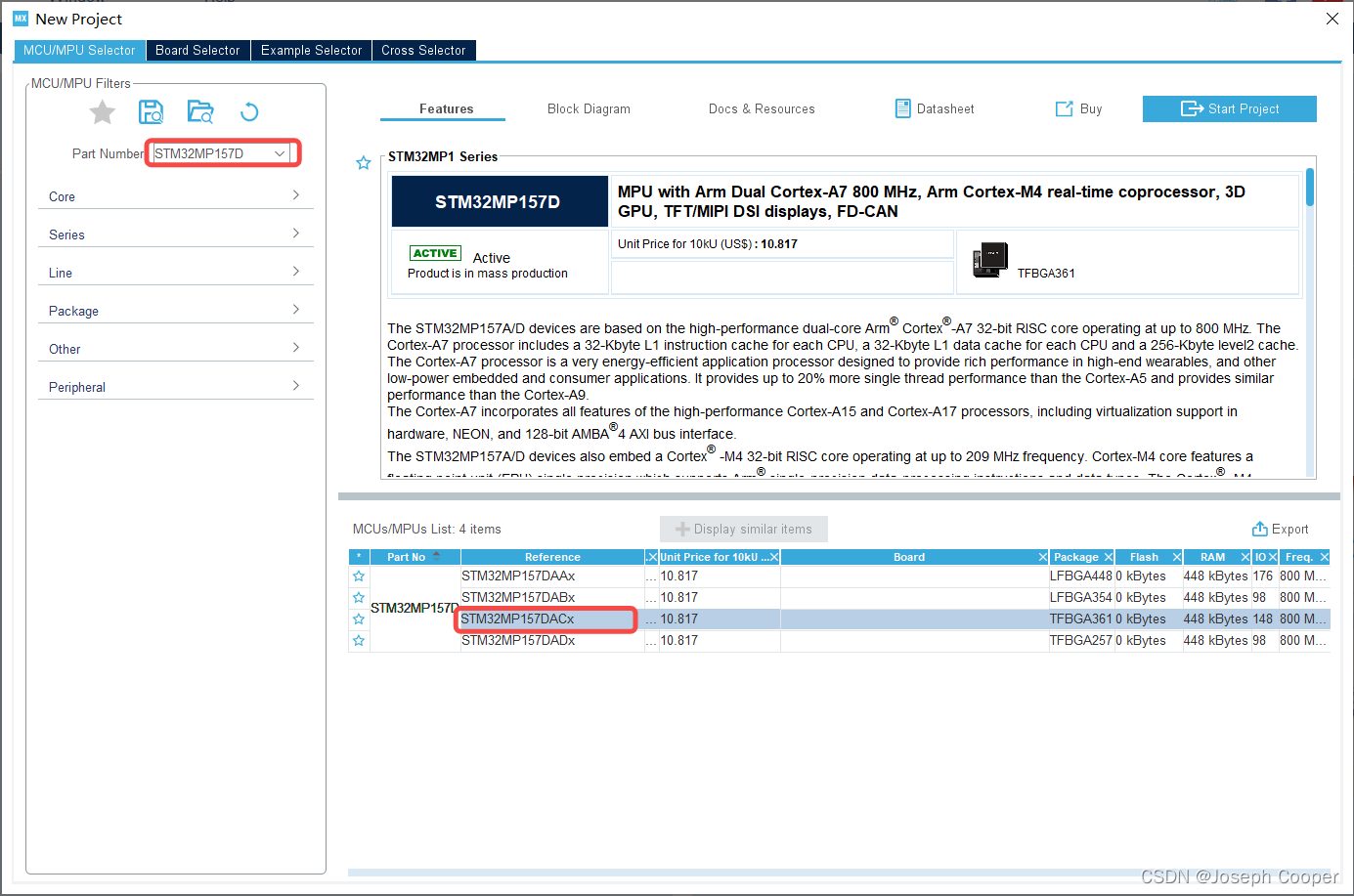

▲STM32CubeMX
这时候打开生成工程目录下的dts文件会发先其中没有和Pinctrl相关的节点,这是因为ST公司对于STM32MP157系列芯片,GPIO为默认模式 不需要再进行配置Pinctrl信息。
a. Pinctrl信息:
b. 设备节点信息(放在arch/arm/boot/dts/stm32mp157c-100ask-512d-lcd-v1.dts根节点下):
        /* LED Test */
        myled {
            compatible = "100ask,leddrv";
            led-gpios = <&gpioa 10 GPIO_ACTIVE_LOW>;
        };
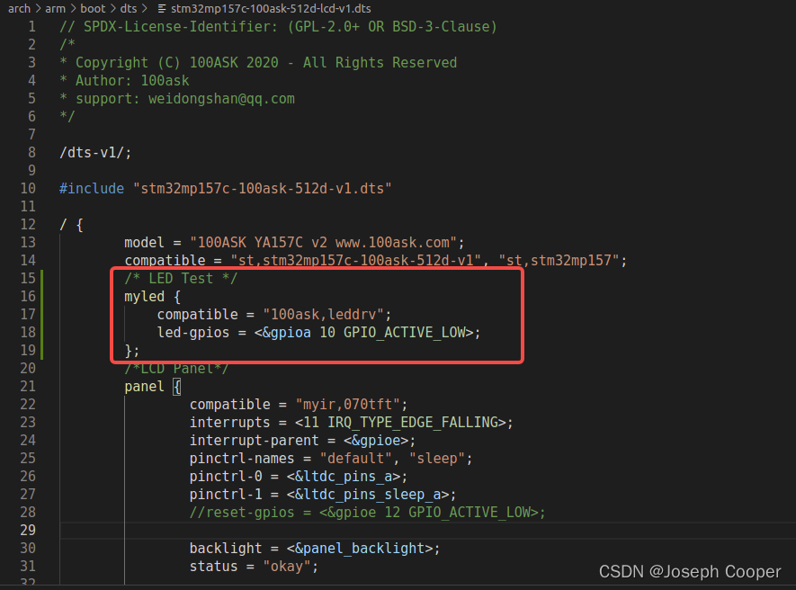
▲stm32mp157c-100ask-512d-lcd-v1.dts
c. 驱动程序
#include <linux/module.h>
#include <linux/platform_device.h>

#include <linux/fs.h>
#include <linux/errno.h>
#include <linux/miscdevice.h>
#include <linux/kernel.h>
#include <linux/major.h>
#include <linux/mutex.h>
#include <linux/proc_fs.h>
#include <linux/seq_file.h>
#include <linux/stat.h>
#include <linux/init.h>
#include <linux/device.h>
#include <linux/tty.h>
#include <linux/kmod.h>
#include <linux/gfp.h>
#include <linux/gpio/consumer.h>
#include <linux/of.h>


/* 1. 确定主设备号                                                                 */
static int major = 0;
static struct class *led_class;
static struct gpio_desc *led_gpio;


/* 3. 实现对应的open/read/write等函数,填入file_operations结构�?                  */
static ssize_t led_drv_read (struct file *file, char __user *buf, size_t size, loff_t *offset)
{
	printk("%s %s line %d\n", __FILE__, __FUNCTION__, __LINE__);
	return 0;
}

/* write(fd, &val, 1); */
static ssize_t led_drv_write (struct file *file, const char __user *buf, size_t size, loff_t *offset)
{
	int err;
	char status;
	//struct inode *inode = file_inode(file);
	//int minor = iminor(inode);

	printk("%s %s line %d\n", __FILE__, __FUNCTION__, __LINE__);
	err = copy_from_user(&status, buf, 1);

	/* 根据次设备号和status控制LED */
	gpiod_set_value(led_gpio, status);

	return 1;
}

static int led_drv_open (struct inode *node, struct file *file)
{
	//int minor = iminor(node);

	printk("%s %s line %d\n", __FILE__, __FUNCTION__, __LINE__);
	/* 根据次设备号初始化LED */
	gpiod_direction_output(led_gpio, 0);

	return 0;
}

static int led_drv_close (struct inode *node, struct file *file)
{
	printk("%s %s line %d\n", __FILE__, __FUNCTION__, __LINE__);
	return 0;
}

/* 定义自己的file_operations结构�?                                             */
static struct file_operations led_drv = {
	.owner	 = THIS_MODULE,
	.open    = led_drv_open,
	.read    = led_drv_read,
	.write   = led_drv_write,
	.release = led_drv_close,
};

/* 4. 从platform_device获得GPIO
 *    把file_operations结构体告诉内核:注册驱动程序
 */
static int chip_demo_gpio_probe(struct platform_device *pdev)
{
	//int err;

	printk("%s %s line %d\n", __FILE__, __FUNCTION__, __LINE__);

	/* 4.1 设备树中定义�? led-gpios=<...>;	*/
    led_gpio = gpiod_get(&pdev->dev, "led", 0);
	if (IS_ERR(led_gpio)) {
		dev_err(&pdev->dev, "Failed to get GPIO for led\n");
		return PTR_ERR(led_gpio);
	}

	/* 4.2 注册file_operations 	*/
	major = register_chrdev(0, "100ask_led", &led_drv);  /* /dev/led */

	led_class = class_create(THIS_MODULE, "100ask_led_class");
	if (IS_ERR(led_class)) {
		printk("%s %s line %d\n", __FILE__, __FUNCTION__, __LINE__);
		unregister_chrdev(major, "led");
		gpiod_put(led_gpio);
		return PTR_ERR(led_class);
	}

	device_create(led_class, NULL, MKDEV(major, 0), NULL, "100ask_led%d", 0); /* /dev/100ask_led0 */

    return 0;

}

static int chip_demo_gpio_remove(struct platform_device *pdev)
{
	device_destroy(led_class, MKDEV(major, 0));
	class_destroy(led_class);
	unregister_chrdev(major, "100ask_led");
	gpiod_put(led_gpio);

    return 0;
}


static const struct of_device_id ask100_leds[] = {
    { .compatible = "100ask,leddrv" },
    { },
};

/* 1. 定义platform_driver */
static struct platform_driver chip_demo_gpio_driver = {
    .probe      = chip_demo_gpio_probe,
    .remove     = chip_demo_gpio_remove,
    .driver     = {
        .name   = "100ask_led",
        .of_match_table = ask100_leds,
    },
};

/* 2. 在入口函数注册platform_driver */
static int __init led_init(void)
{
    int err;

	printk("%s %s line %d\n", __FILE__, __FUNCTION__, __LINE__);

    err = platform_driver_register(&chip_demo_gpio_driver);

	return err;
}

/* 3. 有入口函数就应该有出口函数:卸载驱动程序时,就会去调用这个出口函�? *     卸载platform_driver
 */
static void __exit led_exit(void)
{
	printk("%s %s line %d\n", __FILE__, __FUNCTION__, __LINE__);

    platform_driver_unregister(&chip_demo_gpio_driver);
}


/* 7. 其他完善:提供设备信息,自动创建设备节点                                     */

module_init(led_init);
module_exit(led_exit);

MODULE_LICENSE("GPL");
d. 测试程序

#include <sys/types.h>
#include <sys/stat.h>
#include <fcntl.h>
#include <unistd.h>
#include <stdio.h>
#include <string.h>

/*
 * ./ledtest /dev/100ask_led0 on
 * ./ledtest /dev/100ask_led0 off
 */
int main(int argc, char **argv)
{
	int fd;
	char status;

	/* 1. 判断参数 */
	if (argc != 3)
	{
		printf("Usage: %s <dev> <on | off>\n", argv[0]);
		return -1;
	}

	/* 2. 打开文件 */
	fd = open(argv[1], O_RDWR);
	if (fd == -1)
	{
		printf("can not open file %s\n", argv[1]);
		return -1;
	}

	/* 3. 写文件 */
	if (0 == strcmp(argv[2], "on"))
	{
		status = 1;
		write(fd, &status, 1);
	}
	else
	{
		status = 0;
		write(fd, &status, 1);
	}

	close(fd);

	return 0;
}
实验流程

▲查看platform_devices确认设备树修改生效

▲加载ko,运行APP
这一套流程体验下来对比之前没有使用Pinctrl子系统和GPIO子系统可以很明显的看出其方便之处:
使用GPIO子系统和Pinctl子系统时只需要在通用驱动中调用函数即可,省去了繁琐的寄存器操作

北京人形旗下天工造物具身智能开源社区,聚焦具身天工与慧思开物两大平台
更多推荐
 1
1 0
0- 0


 已为社区贡献13条内容

所有评论(0)