Halcon 定位加二位测量找直线
·
图像:
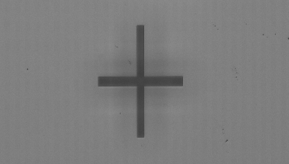
代码:
dev_close_window ()
dev_open_window (0, 0, 512, 512, 'black', WindowHandle)
*加载图像
read_image (Image,'//DESKTOP-V21FG2T/Share/2.bmp')


threshold(Image,Region, 50, 100)
connection(Region, ConnectedRegions)
select_shape(ConnectedRegions, SelectedRegion, 'area', 'and', 100000, 9999999)

* 获取最小外接矩形(水平矩形)
smallest_rectangle1 (SelectedRegion, Row1, Column1, Row2, Column2)

Width := Column2 - Column1 + 1
Height := Row2 - Row1 + 1
* 获取四条边的中心点
* 上边中心点
TopCenterRow := Row1
TopCenterCol := (Column2+Column1) / 2

* 下边中心点
BottomCenterRow := Row2
BottomCenterCol := (Column2+Column1) / 2

* 左边中心点
LeftCenterRow := (Row2+Row1) / 2
LeftCenterCol := Column1

* 右边中心点
RightCenterRow := (Row2+Row1) / 2
RightCenterCol := Column2
*界面操作得到测量区域,转到视野上画线
* draw_line (WindowHandle, Row1, Column1, Row2, Column2)
* shapePararm:=[Row1,Column1,Row2,Column2]
* 创建一个空元组来存储选择的对象
gen_empty_obj(EmptyObject)
* 确定了测量区域的上线的中心和下线的中心
shapePararm:=[TopCenterRow,TopCenterCol,BottomCenterRow,BottomCenterCol]
* 确定了测量区域的左线的中心和右线的中心
shapePararm1:=[LeftCenterRow,LeftCenterCol,RightCenterRow,RightCenterCol]
params:=[shapePararm,shapePararm1]
for i := 0 to 1 by 1
    * 提取当前参数

*创建直线模型
create_metrology_model (MetrologyHandle)
*设置直线模型图像大小,即需要被检测的图像大小
set_metrology_model_image_size (MetrologyHandle, Width, Height)
*添加线模型通用测量对象  sharp参数设置为line    Index:输出创建测量对象的索引值
if (i == 0)
        * 处理第一条参数(i=0)
        add_metrology_object_generic (MetrologyHandle, 'line', shapePararm, 700, 10, 1, 10, [], [], Index)
    elseif (i == 1)
        * 处理第二条参数(i=1)
        add_metrology_object_generic (MetrologyHandle, 'line', shapePararm1, 700, 10, 1, 10, [], [], Index)
    endif


*找线方式,暗 / 亮(positive)或亮 / 暗(negative)边缘,'uniform' 表示同时检测并分别拟合
set_metrology_object_param (MetrologyHandle, 'all','measure_transition', 'all')
*设置卡尺数量
set_metrology_object_param (MetrologyHandle, 'all', 'num_measures', 30)
*拟合数,每个计量对象最多拟合的有效实例数,达到后停止拟合
set_metrology_object_param (MetrologyHandle, 'all', 'num_instances', 4)
*高斯平滑系数,值越大边缘越清晰,越不容易找到边缘,值越小,干扰边缘越多
set_metrology_object_param (MetrologyHandle, 'all', 'measure_sigma', 2)
*测量双立方插入值,区别于bilinear双线性
set_metrology_object_param (MetrologyHandle, 'all', 'measure_interpolation', 'bicubic')
*边缘振幅最小值,最小边缘幅度越大,要求找到的边缘越锐利(灰度变化明显),反而越不容易找到边缘
set_metrology_object_param (MetrologyHandle, 'all', 'measure_threshold', 20)
*取值 all,first,best,last
set_metrology_object_param (MetrologyHandle, 'all', 'measure_select', 'all')
*判定有效拟合实例的最低分数(检测边缘数 / 最大测量区域数)
set_metrology_object_param (MetrologyHandle, 'all', 'min_score', 0.4)
*开始找边缘
apply_metrology_model (Image, MetrologyHandle)
*获取模型的计量区域和边缘结果
get_metrology_object_measures (Contours, MetrologyHandle, 'all', 'all', Rows, Columns)
*把所有点显示出来
gen_cross_contour_xld (Cross, Rows, Columns, 6, 0.785398)


* 如果需要拟合直线
*  gen_contour_polygon_xld (Contour, Rows, Columns)
*  fit_line_contour_xld (Contour, 'drop', -1, 0, 5, 2, TempRowBegin, TempColBegin, TempRowEnd, TempColEnd, TempNr, TempNc, TempDist)
             * 计算拟合的直线和点之间的距离
*             distance_pl (Rows, Columns, TempRowBegin, TempColBegin, TempRowEnd, TempColEnd, Distance)
*             tuple_max (Distance, Max)
            * 在联系的删除点中是不是有足够的点来拟合


            * 删除不符合点到直线距离的点
*             tuple_less_elem (Distance, Max/2, Less)
*             tuple_find (Less, 0, Indices)
*             tuple_remove (Rows, Indices, ValidRows)
*             tuple_remove (Columns, Indices, ValidCols)

*得到线的起点坐标并显示出来
get_metrology_object_result (MetrologyHandle, 0, 'all', 'result_type', 'all_param', Parameter)
*获模型计量对象的结果轮廓
get_metrology_object_result_contour (Contour, MetrologyHandle, 0, 'all', 5)

select_obj(Contour, ObjectSelected1, 1)
select_obj(Contour, ObjectSelected2, 2)
concat_obj(EmptyObject, ObjectSelected1, TempObject)
concat_obj(TempObject, ObjectSelected2, EmptyObject)
* EmptyObject := [EmptyObject, ObjectSelected1, ObjectSelected2]
* select_obj(Contour, ObjectSelected3, 3)
*释放测量句柄,很重要否则导入C#代码运行没多久就会崩溃程序
clear_metrology_object (MetrologyHandle, 'all')
endfor
dev_clear_window()
dev_display(Image)
dev_display(EmptyObject)
* 提取直线参数
Lines1 := []
select_obj(EmptyObject, Line, 1)
fit_line_contour_xld(Line, 'tukey', -1, 0, 5, 2, Row1, Col1, Row2, Col2, _, _, _)
Lines1 := [Lines1, [Row1, Col1, Row2, Col2]]

* 获取线段角度(返回弧度)
orientation_xld(Line, AngleRad)

* 转换为角度(°)
AngleDeg := AngleRad * 180 / 3.1415926535

Lines2 := []
select_obj(EmptyObject, Line, 2)
fit_line_contour_xld(Line, 'tukey', -1, 0, 5, 2, Row1, Col1, Row2, Col2, _, _, _)
Lines2 := [Lines2, [Row1, Col1, Row2, Col2]]

Lines3 := []
select_obj(EmptyObject, Line, 3)
fit_line_contour_xld(Line, 'tukey', -1, 0, 5, 2, Row1, Col1, Row2, Col2, _, _, _)
Lines3 := [Lines3, [Row1, Col1, Row2, Col2]]

Lines4 := []
select_obj(EmptyObject, Line, 4)
fit_line_contour_xld(Line, 'tukey', -1, 0, 5, 2, Row1, Col1, Row2, Col2, _, _, _)
Lines4 := [Lines4, [Row1, Col1, Row2, Col2]]

*计算交点
intersection_lines (Lines1[0], Lines1[1], Lines1[2], Lines1[3], Lines3[0], Lines3[1], Lines3[2], Lines3[3],  Row13, Column13, IsOverlapping)
intersection_lines (Lines1[0], Lines1[1], Lines1[2], Lines1[3], Lines4[0], Lines4[1], Lines4[2], Lines4[3],  Row14, Column14, IsOverlapping)

intersection_lines (Lines2[0], Lines2[1], Lines2[2], Lines2[3], Lines3[0], Lines3[1], Lines3[2], Lines3[3],  Row23, Column23, IsOverlapping)
intersection_lines (Lines2[0], Lines2[1], Lines2[2], Lines2[3], Lines4[0], Lines4[1], Lines4[2], Lines4[3],  Row24, Column24, IsOverlapping)

AverageRow := (Row13 + Row14 + Row23 + Row24) / 4
AverageColumn := (Column13 + Column14 + Column23 + Column24) / 4

dev_clear_window()
dev_display(Image)
gen_cross_contour_xld (Cross1, AverageRow, AverageColumn, 200, AngleRad)
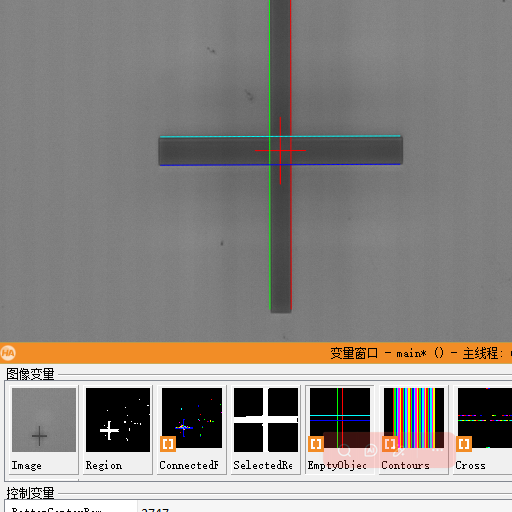
效果:

北京人形旗下天工造物具身智能开源社区,聚焦具身天工与慧思开物两大平台
更多推荐
 1
1 0
0- 0


 已为社区贡献2条内容

所有评论(0)